Overview
Carbon dioxide (CO2) gas was used as a contrast agent in the venous circulation in the 1950s and 1960s to delineate the right heart for evaluation of suspected pericardial effusion. This imaging developed from animal and clinical studies, which demonstrated that CO2 use was safe and well tolerated with peripheral venous injections.
In the 1970s, CO2 was used as an intra-arterial contrast agent. With the advent of digital subtraction angiography (DSA) in 1980, CO2 angiography became a useful diagnostic tool, particularly in patients who were hypersensitive to iodinated contrast material or whose renal function was compromised. Now, with the availability of high-resolution DSA and a reliable gas delivery system, CO2 angiography has become widely used for vascular imaging and endovascular procedures.
CO2 is used as an alternative to iodinated contrast media in patients who are at high risk for contrast-induced nephropathy and in cases in which a patient has a known allergy to contrast media. [1, 2]
Because the use of CO2 is not associated with nephrotoxicity or allergic reactions, it is increasingly being used as a contrast agent for aortography, as well as for outflow assessment, renal arteriography, and visceral angiography. The gas is the preferred contrast agent for central venography of the upper extremity; for wedged hepatic venography to visualize the portal venous system before transjugular intrahepatic portosystemic shunt (TIPS); for fine-needle TIPS procedures and splenoportography [1, 3, 4]
CO2 is used to guide various vascular interventions, including angioplasty and stent placement, transcatheter embolization, vena cava filter placement and endovascular abdominal aortic aneurysm (AAA) repair.
CO2 should not be used as an arterial contrast agent in sites above the diaphragm because of the risk of gas embolism of the spinal, coronary, and cerebral arteries. The inadvertent entry of CO2 into the cerebrovascular circulation during angiography can cause fatal brain injury. [5] CO2 may be delivered by the hand-held syringe method, by the plastic bag system, or by the CO2mmander and AngiAssist. These delivery systems are safe if used correctly. Because air is poorly soluble, air contamination must be prevented during the delivery of CO2. Thorough understanding of the physical properties of CO2 and facile catheterization technique are essential in obtaining optimal CO2 imaging for both diagnosis and intervention. [5, 2, 6, 7, 8, 9, 10, 11, 12, 13, 14]
CO2 should not be combined with nitrous oxide for sedation because when nitrous oxide mixes with CO2, the solubility of CO2 in the blood is reduced, preventing its excretion. [4]
Chemical and physical properties of CO2
When CO2 is injected into the blood, it is combined with water to produce carbonic acid. It becomes bicarbonate (HCO3-) in the blood stream; bicarbonate reverts to CO2 before being expelled out of capillaries into the lung. Carbonic anhydrase catalyzes the conversion of CO2 to bicarbonate and protons. CO2 is eliminated by the lungs in a single pass. However, CO2 bubbles that were injected into the venous system may enter the systemic circulation via the patent foramen ovale or intracardiac septal defects. [2]
CO2 is a colorless and odorless gas, and it cannot be visually distinguished from air. The incorrect application of technique may result in air contamination, which may cause serious complications. A thorough understanding of the unique physical properties of CO2 is necessary for the safe and effective performance of CO2 angiography and CO2-guided vascular interventions. CO2 is approximately 20 times more soluble than oxygen. When injected into a vessel, CO2 bubbles completely dissolve within 2-3 minutes; however, if the gas is trapped in a large abdominal aneurysm, it may persist, allowing gas exchange between the CO2 and nitrogen in the blood. This exchange may result in colonic ischemia, as a result of occlusion of the inferior mesenteric artery. Two to three minutes should elapse between injections of CO2 to prevent the localized accumulation of gas bubbles, which may produce a significant gas embolism, particularly in the pulmonary artery.
CO2 is compressible during injection; it expands in the vessel as it exits the catheter. Clearing the fluid of the catheter by using 3-5 cc of CO2 before injection reduces the explosive delivery. The explosive delivery is unlikely to cause vascular damage, but it may contribute to discomfort during the injection. The low viscosity and compressibility of the gas accounts for the greater sensitivity of CO2 as a contrast agent in detecting the source of bleeding (gastrointestinal tract and traumatic bleeding in the liver, spleen and pelvis), as compared to iodinated contrast material.
CO2 is lighter than blood plasma; therefore, it floats above the blood. When injected into a large vessel, such as the aorta or inferior vena cava, CO2 bubbles flow along the anterior part of the vessel, with incomplete blood displacement along the posterior portion. Because of their anterior point of origin, the celiac and superior mesenteric arteries fill well with small volumes (< 15 cc) of CO2. If gas fails to fill the renal artery originating from the posterolateral aspect of the aorta, the patient must be rotated so that the side of the renal artery to be visualized is elevated above the level of the injection site. If the renal artery remains unfilled, catheterization of the artery and selective injection are indicated.
The buoyancy of the gas is not a problem when the vessel to be imaged is smaller than 10 mm in diameter, because the gas bubbles tend to displace the blood in more than 80% of the lumen. Elevation of the lower extremity to 15-20° in conjunction with the intra-arterial injection of 100-200 µg of nitroglycerin enhances gas flow and filling of the distal arteries in the lower extremity.
CO2 is approximately 400 times less viscous than iodinated contrast medium. The low viscosity permits manual gas injection with small-bore catheters and between the catheter and guide wire. Doses of CO2 required for aortic imaging may be manually injected by using a 4-Fr or 5-Fr end-hole diagnostic catheter. The low viscosity accounts for better filling of collateral vessels for both arterial and venous occlusive diseases and for portal vein visualization through the hepatic sinusoids after wedged hepatic or liver parenchymal injection with CO2.
Iodinated contrast medium mixes with blood when injected into a vessel and becomes diluted, making it less dense as it travels through collateral vessels. By contrast, CO2 does not mix with blood, and therefore, it does not become diluted by collateral flow.
Advantages of carbon dioxide
CO2 is less dense than iodinated contrast medium, thus requiring digital subtraction angiography with good contrast resolution for gas imaging. The overall quality of CO2 vascular images is slightly less than that obtained with contrast medium. Usually, multiple hand injections are required, and the radiation exposure to the operator and patient may be increased. However, CO2 has several notable advantages, as compared to iodinated contrast medium, as noted below.
CO2 causes no allergic reaction. Because CO2 is a natural by-product, it cannot cause a hypersensitivity reaction. Therefore, CO2 is an ideal alternative to iodinated contrast medium for patients who have a history of allergic reactions. No steroid preparation is needed when CO2 is used.
CO2 causes no renal toxicity. Experimental and clinical findings indicate that the selective injection of CO2 into the aorta or into the renal artery is safe and causes no renal injury, even in patients with diabetes or compromised renal function. Therefore, the gas is the preferred contrast agent for renal artery angioplasty and stent placement. [15]
CO2 causes no hepatic toxicity. The authors have personally used CO2 as a contrast agent for celiac, splenic, superior mesenteric, and hepatic arteriograms for patients with a variety of disorders. No injuries to the hepatic parenchyma have occurred after the injection of CO2.
Unlimited amounts of CO2 may be used for vascular imaging because the gas is effectively eliminated by means of respiration. However, the operator should allow sufficient time for its clearance. A minimum of 2 minutes is needed for the first CO2 dose to completely dissolve before another dose is injected. CO2 is particularly useful for patients with compromised cardiac and renal function who are undergoing complex vascular interventions.
Because of the low viscosity, CO2 angiography is more sensitive in detecting gastrointestinal and traumatic pelvic bleeding than iodinated contast medium. CO2 can be injected through a small catheter, such as 3-Fr microcatheter, for diagnostic angiography and CO2-guided endovascular interventions. When injected into the iliac or femoral artery, CO2 can visualize both the proximal and distal vessels. For example, CO2 injected into the proximal femoral or external iliac artery will reflux centrally filling the aorta and the contralateral iliac and femoral artery. CO2 reflux angiography with a gas injection into a segmental renal artery is used to fill the proximal renal artery originating from the posterolateral aspect of the aorta.
Disadvantages of carbon dioxide
After injection, CO2 floats on the surface of blood, so that abnormalities of the dependent portions of vessels may be missed. Also, imaging of arteries such as the lumbar and some renal arteries, which follow a posterior course, may only fill with the patient in a more decubitus position. [4]
CO2 can cause an underestimation or an overstimulation of vessel caliber and has greater interobserver variability in determining vessel caliber when compared with liquid contrast or intravascular ultrasound. CO2 also has a lower accuracy rate for characterizing stenoses than does liquid contrast. [4]
CO2 passing through a vascular bifurcation dissipates and can simulate a stenosis. In cases of the presence of a physiologic shunt, CO2 can mimic an anatomic fistula. [4]
Techniques
Patient preparation
No specific patient preparation is required for CO2 angiography. The standard preparation for catheter angiography is used. Patients with a history of allergy to contrast material do not require steroid preparation. CO2 may be used as a contrast agent for outpatient angiography.
Contraindications
There are no absolute contraindications to the use of CO2. CO2 should not be used in the thoracic aorta and in arteries above the diaphragm because of the risk of spinal, coronary, and carotid artery gas embolism. CO2 should be used with caution in patients with pulmonary insufficiency or pulmonary hypertension because a diagnostic dose of CO2 may cause an increase in pulmonary arterial pressure. CO2 should not be used in patients with an intracardiac septal defect or a pulmonary arteriovenous malformation because of the possibility of paradoxical gas embolism.
Sedation and analgesia
Heavy sedation should be avoided during CO2 angiography. Respiratory depression and hypotension caused by air contamination may be mistaken for adverse effects of the sedatives and/or analgesics.
Patient monitoring
All patients undergoing CO2 angiography should be monitored with ECG and pulse oximetry; blood pressure, respiratory rate, and heart rate should also be monitored. Capnograms should be obtained if the patient is intubated. The blood pressure should be checked before the initial injection of CO2, as well as 1 minute after each CO2 injection.
A significant change in any monitoring parameter suggests either that the doses of CO2 were excessive or that air contamination has occurred. Capnography (ETCO2) is very useful during CO2 angiography because it allows the monitoring of both ventilatory and hemodynamic functions in real time. Microcap is a handheld capnometer. It uses microstream infrared spectroscopy to measure the respiratory rate and ETCO2 during exhalation. A similar capnometer, Capnocheck, is also available.
Carbon dioxide delivery
The CO2 delivery system should be filled with 99.99% medical-grade CO2 from a disposable cylinder. The cylinder is supplied with highly pure gas, a valve, a regulator, a gas gauge, and a metal diaphragm with the regulator set at 18 psi. Because of the risk of injection of large volumes of CO2, the catheter should not be directly connected to the CO2 cylinder, which contains a large volume of CO2 at very high pressure. CO2 may be delivered into a vessel by use of a hand-held syringe, by the plastic bag system, or by CO2mmander with the AngiAssist (see the images below).
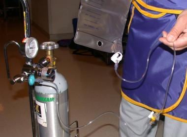 The plastic bag is connected to the carbon dioxide cylinder through a 0.2 micrometer filter. The 3-way stopcock between the cylinder and the bag allows filling and emptying of the bag with carbon dioxide to remove residual air from the bag.
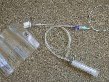 Plastic bag and delivery system (Custom Waste Bag and Contrast Delivery Set, Merit Medical Systems, Inc. South Jordan, Utah). The bag is connected to the connecting tube where the injection syringe is located. The 3-way stopcock just distal to the check valve permits flushing and the injection of contrast medium into the catheter.
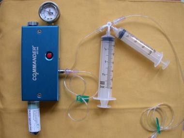 The CO2mannder (PMDA, LLCk, Ft. Myers, Fla) is an FDA-approved portable medical CO2 delivery system, allowing gas delivery at a low pressure through the AngiAssist. The unique stopcock system with valves controlling the direction of gas flow with the use of a 60-cc reservoir syringe and a 30-cc injection syringe allow safe delivery of CO2 in a nonexplosive fashion.
When a syringe is used, it should be filled directly from a CO2 cylinder. CO2 should not be aspirated into the syringe because this may cause air contamination. When the syringe has been filled with CO2, its pressure should be reduced to the atmospheric level by quickly opening and closing the stopcock. The CO2 -filled syringe should not be left on the table with the stopcock open before injection, because the CO2 in the syringe (which has a CO2 concentration of >99%) is rapidly replaced with air (which has a CO2 concentration of 0.03%). The syringe method is inconvenient when multiple injections are necessary.
In the plastic bag delivery system, the collection bag is filled with CO2 and is connected to the reservoir port of the fluid management system. This system has airtight connections with the check valves, the injection port, the bleed-back port, and the catheter port. The check valves reduce the need for stopcock manipulation, which in turn reduces the risk of air contamination. The bag must be tightly connected to the reservoir port of the delivery system to prevent air contamination. The bleed-back port near the catheter port allows normal saline or contrast medium injections. If CO2 is to be injected with a guide wire in the catheter, a Y-connector is connected to the injection port. The bag should be filled and emptied with CO2 3 times before the final filling to remove air from the bag.
The injection rate depends on the diameter, length, and flow of the vessels being imaged. For an abdominal aortogram or an inferior vena cavogram, 30-40 cc of CO2 is injected. When imaging aortic branches (celiac, superior mesenteric, renal arteries) or arteries of the lower extremity, 20-30 cc is used. Because of the low viscosity of the gas, CO2 may be injected through a 3-Fr microcatheter for selective and superselective angiography and for selective arterial embolization.
Digital subtraction angiography (DSA) should be used for CO2 imaging. If available, a 1024 X 1024 digital subtraction angiographic system and magnification technique should be used. Stacking software for integrating a series of images has solved problems associated with the breakup of CO2 bubbles after injection.
Respiratory motion and peristalsis become significant problems in mesenteric CO2 angiography. Motion occurring between the time that the baseline image is made and the time that the CO2 image is made causes marked degradation in the quality of the imaging. Additional mask images should be obtained to decrease motion artifacts by using new mask imaging subtraction. Superselective CO2 injection into the mesenteric arterial branch with gas reflux can also improve the quality of the images. Intravenous administration of glucagon at the dose of 0.5-1 mg before CO2 injection improves mesenteric CO2 angiography by decreasing peristalsis.
Rapid exposures (4 to 6 frames per second) should be obtained, and superselective injection of CO2 as close to the target vessel as possible should be performed to optimize CO2 imaging. Elevation of target vessels 15-20° above the level of the angiographic table, as well as the intra-arterial administration of 100-150 µg of nitroglycerin, may improve filling of the peripheral arteries in the lower extremities. [16, 17, 18] Proximal arteries can be imaged by refluxing CO2 from a peripheral injection.
In a pilot study of 4 patients with peripheral artery disease (PAD) and impaired renal function (average eGFR 25.5 ± 11.2 ml/min/1.73 m2), images from CO2-assisted lower limb interventions using DSA and digital variance angiography (DVA) were visually evaluated and compared by 5 expert readers. The DVA images were at lower frame rates (1-3 FPS) than DSA (4-6 FPS) and preferred based on their diagnostic value and usefulness for therapeutic decision making in 85.2% and 83.9% of all comparisons, retrospecively. The authors concluded that DVA may be useful in facilitating more accurate diagnoses and reducing radiation exposure. [19]
Clinical Applications
CO2 is used widely as an intravascular contrast agent for imaging both the arterial and venous circulations, particularly for patients with renal insufficiency and for patients who have a history of hypersensitivity to iodinated contrast medium. CO2 may be used as a contrast agent for diagnostic arteriography, venography, and various vascular interventions, including renal stenting, superior mesenteric artery stenting, and endovascular aneurysm repair (EVAR). A summary of the clinical applications of CO2 as a contrast agent for vascular diagnosis and interventions follows. [20, 21, 22, 23, 24, 25, 26, 27, 28, 29, 30, 31]
CO2 is frequently used as an alternative contrast agent for aortography and runoff in patients with contrast allergy and renal insufficiency (see the image below). In most patients, all outflow studies may be done with CO2. Small amounts of iodinated contrast medium are used if needed for additional vascular information.
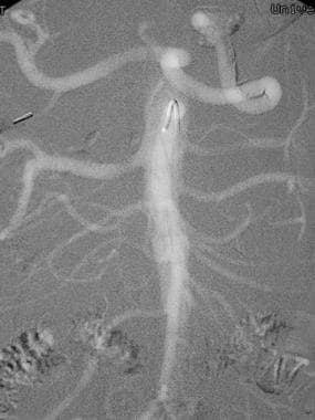 This frontal carbon dioxide digital subtraction aortogram shows a single right renal artery with a mild stenosis at the origin and 2 left renal arteries. The celiac and superior mesenteric arteries fill nicely because of their anterior origin.
The technique involves the percutaneous retrograde catheterization of the femoral artery and introduction of a 4-Fr end-hole catheter, such as a shepherd hook or a Cobra-shaped catheter. An abdominal aortogram is performed with the injection of 30-40 cc of CO2 injected at the rate of 15-20 cc per second in the anteroposterior and lateral projections. Filming is made at the rate of 4 frames per second. Then, CO2 is injected into the distal aorta or the iliac artery to image the iliac and femoral arteries. The common and external iliac arteries can be well visualized by reflux from a common or superficial femoral artery injection. The catheter is then advanced into the contralateral superficial femoral artery for a runoff study.
If the infrapopliteal arteries are poorly visualized with a proximal injection, a 3-Fr microcatheter is advanced coaxially into the popliteal artery to image the tibial and peroneal arteries. The retrograde approach is then converted to the antegrade approach; CO2 angiography is performed in the same fashion as on the contralateral side. For imaging of the iliac, femoral, and popliteal arteries, 20 cc of CO2 is selectively injected.
Elevation of the legs and the intra-arterial injection of nitroglycerin (100-150 µg) allow improved visualization of the tibial and plantar branches. Because of its buoyancy and low viscosity, CO2 may provide better filling of collateral arteries and distal branches than iodinated contrast medium provides. In 92% of cases, the vascular information provided by CO2 angiography is adequate for a surgical or endovascular intervention.
CO2 is most frequently used as a contrast agent for renal DSA in patients who are allergic to contrast medium or who have renal failure (see the images below). CO2 allows visualization of the proximal renal arteries and renal artery stenoses. Because of the posterior position of the kidney relative to the aorta where CO2 is injected, the distal renal arteries do not fill well, because of the buoyancy of the gas.
 This carbon dioxide digital subtraction angiogram shows patency of the external iliac and transplanted renal arteries.
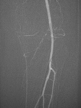 This carbon dioxide digital subtraction angiogram (stacked image) of the left lower extremity shows the popliteal, anterior tibial, peroneal, and posterior tibial arteries.
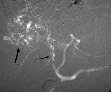
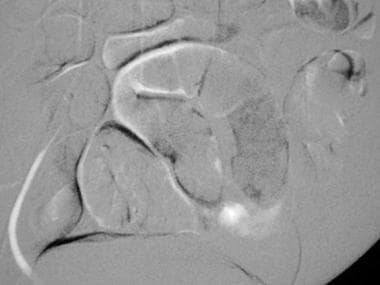 This mesenteric carbon dioxide digital subtraction angiogram in a patient with small-bowel bleeding shows extravasation of carbon dioxide gas bubbles. Embolization with coils stopped the bleeding.
After percutaneous femoral artery catheterization, a 4-Fr or 5-Fr catheter such as the shepherd hook catheter is advanced into the abdominal aorta; 30 to 40 cc of CO2 is then injected into the aorta with the plastic bag delivery system in the anteroposterior projection. If filling of the renal artery is suboptimal, the patient may be rotated so as to orient the renal artery above the aorta.
Cross-table lateral imaging with the patient in the lateral decubitus position usually provides excellent filling of the renal artery. Selective renal DSA is performed with the injection of CO2 (20 cc) into the main renal artery. For visualization of the segmental renal artery branches, a more distal injection is needed.
Following renal angioplasty and stent placement guided by CO2, CO2 injection distal to the stent allows visualization of the main renal artery by reflux. CO2 angiography may allow visualization of vascular renal cell carcinoma, as well as tumor invasion of the renal vein or inferior vena cava. CO2 may also allow visualization of the intrarenal arteriovenous fistula, stenosis, and aneurysm.
Doppler ultrasonography and magnetic resonance (MR) angiography are used as the initial diagnostic modality for the evaluation of suspected transplant renal artery stenosis. Because of the location of the renal artery anterior to the iliac artery injection site, CO2 injection usually fills the transplant renal artery. After either ipsilateral or contralateral femoral artery catheterization, CO2 is injected into the external iliac artery using an end-hole catheter in the anteroposterior and ipsilateral oblique projection. An injection of CO2 into the renal artery better fills the renal artery and its branches. If a hemodynamically significant renal artery stenosis is found, balloon angioplasty and stenting can be performed using CO2 as a contrast agent. Completion angiography is performed with the injection of CO2 into the renal artery or into the external iliac artery.
Carbon dioxide angiography has value in selected situations requiring visceral angiography. CO2 aortography and visceral arteriography have been found to be useful in the evaluation of the arterial anatomy, as well as in the evaluation of chronic mesenteric ischemia, aneurysms, arteriovenous fistula, and bleeding.
From the femoral artery approach, 30-40 cc of CO2 is injected 1 to 2 cm above the celiac axis using an end-hole catheter with the plastic bag delivery system; imaging is acquired in the anteroposterior and lateral projections (see the images below). Lateral aortography is obtained during both full inspiration and expiration to evaluate median arcuate ligament compression on the celiac artery. Median arcuate ligament compression produces an extrinsic, concave impression on the cranial aspect of the celiac axis just distal to its origin at the expiratory aortogram.
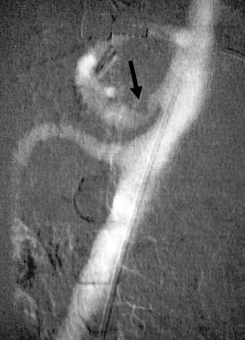 CO2 aortogram (cross-table lateral DSA) demonstrates narrowing of the celiac axis with concave impression (arrow) secondary to median arcuate ligament compression.
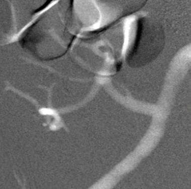
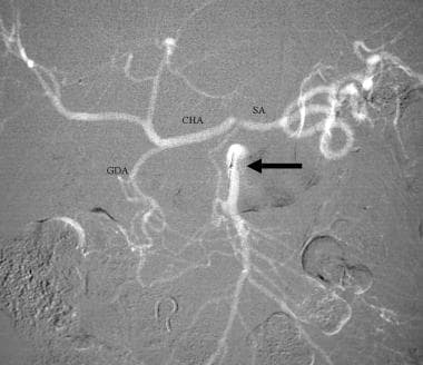 Celiac stenosis caused by median arcuate ligament compression. CO2 superior mesenteric DSA demonstrates filling of the gastroduodenal (GDA), common hepatic (CHA), and splenic (SA) arteries from the superior mesenteric artery (arrow).
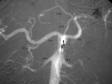 CO2 celiac DSA. CO2 refluxes from the celiac axis back into the aorta, filling the superior mesenteric and bilateral renal arteries (RRA and LRA). The gastroduodenal (GDA), common hepatic (HA), splenic (SA), left gastric (LGA) and replaced left hepatic (LHA) arteries are visualized.
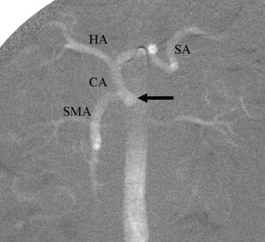 CO2 aortogram demonstrates celicomesenteric trunk, common origin of the celiac axis (CA) and superior mesenteric arteries. Common hepatic (HA) and splenic (SA) arteries are visualized.
Because of its low viscosity, CO2 DSA is more sensitive than iodinated contrast medium in detecting bleeding from the GI tract, liver, and spleen. If extravasation is seen on the CO2 aortogram, selective arteriography is performed with CO2. Repeat arteriography is usually needed with iodinated contrast medium to provide a vascular road map before superselective catheterization of the bleeding artery for embolization. Use of CO2 allows visualization of the visceral arterial stenoses and collaterals. CO2 is useful in visualizing hepatocellular carcinoma and transcatheter chemoembolization (TACE).
CO2 angiography is useful in various oncologic interventions. The low viscosity of CO2 allows the injection of the gas through a 3-Fr microcatheter for superselective angiography (see the images below). CO2 may be used to assist selective embolization of renal cell carcinoma and its bone metastases and of hepatocellular carcinoma. It is also useful in placing hepatic arterial infusion catheters; for embolization of the gastroduodenal artery; for evaluation of a malfunctioning hepatic artery pump; and in hepatic arterial redistribution procedures.
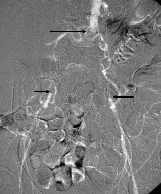 This carbon dioxide digital subtraction arteriogram in a patient with occlusion of the aorta (longer arrow) and both common iliac arteries (shorter arrows) was obtained with the injection of 30 cc of CO2 in the left external iliac artery using a 3F dilator. Because of the low viscosity, the gas flows well through the collaterals to the aorta and contralateral iliac arteries.
 Right hepatic DSA with CO2 demonstrates a vascular tumor in the right hepatic lobe (arrow). The shorter arrow points at the tip of the microcatheter passed coaxially through the 5-Fr catheter positioned in the celiac axis. CO2 refluxed, filling the left hepatic and common hepatic arteries.
Because of the low viscosity, CO2 may be injected between the guide wire and catheter, allowing imaging before, during, and after angioplasty. CO2 may also be injected through the sheath to guide angioplasty and stent placement. The plastic bag system provides multiple rapid injections with the guide wire in place. CO2 has definitive advantages over iodinated contrast medium, in that its use is not associated with risks of renal toxicity or allergic reactions.
CO2 is very useful for renal angioplasty and stent placement (see the image below). The plastic bag system allows multiple injections in various oblique projections so as to accurately position the stent. When CO2 is injected into the renal artery, the gas always fills the renal artery with reflux of the gas into the aorta. This allows visualization of the orifice of the renal artery, which is helpful for accurately deploying the stent.
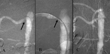 Carbon dioxide guided stent placement of right renal artery stenosis. A. CO2 DSA demonstrates orificeal stenosis of right renal artery (arrow). B. DSA with the injection of CO2 through the sheath demonstrates the stent in good position (arrow). C. After stent deployment, the renal artery is widely patent.
After an aortogram is obtained, the renal artery is catheterized with a 4-Fr or 5-Fr shepherd hook or a Cobra catheter, and a dual pressure recording is obtained in the renal artery distal to the stenosis and the aorta. If a significant pressure gradient is present, a 6-Fr sheath is advanced into the abdominal aorta over a 0.035-in Rosen wire. A balloon-expanding stent of appropriate diameter and length is then advanced into the renal artery stenosis. CO2 is injected through the sheath and is imaged in multiple projections to precisely place the stent.
After stent deployment, a 4-Fr catheter (renal access Cobra catheter) is advanced into the renal artery, and the pressure gradient between the renal artery and the aorta is measured. If no significant gradient is present, CO2 is injected through the Cobra catheter into the renal artery to visualize the stented renal artery.
EVAR is a well-accepted treatment modality for AAA. The use of CO2 as an alternative contrast agent during EVAR may reduce the risk of renal failure. Because of its low viscosity, CO2 may be injected via a 4-Fr Cobra catheter or through the introducer, which is preloaded with a stent graft, so as to demonstrate the renal and hypogastric artery before deployment of the stent graft. After deployment, a completion aortogram is performed with CO2, using the Cobra catheter, to demonstrate the patency of the renal and hypogastric arteries and to identify any endoleak (see the images below).
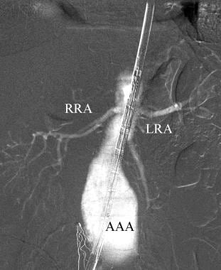 This carbon dioxide aortogram obtained with the injection of CO2 through the sheath during endovascular aortic repair demonstrates the right (RRA) and left (LRA) renal arteries. AAA=abdominal aortic aneurysm
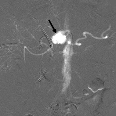 CO2 celiac angiogram in a patient with gastrointestinal bleeding following hepatic tumor resection shows a large pseudoaneurysm (arrow) arising from the distal celiac axis. Embolization controlled the bleeding
CO2 digital subtraction venography is safe and useful in the evaluation of the central veins of the upper extremities. Because of its low viscosity and its buoyancy, CO2 may be injected through a 21-gauge peripheral IV access device for diagnostic central venography. The injection of CO2 into a vein of small diameter may cause pain at the injection site. It is preferable to obtain IV access via the antecubital vein.
When 20-30 cc of CO2 is injected into the antecubital vein, the subclavian vein becomes well filled within 5 seconds of the injection (see the image below). Occasionally, CO2 reflux occurs into the contralateral innominate vein. CO2 is also used for upper-extremity venography before surgical placement of an arteriovenous fistula, before transvenous pacer insertion, and before placement of a central venous catheter in selected patients. For visualization of the entire venous system of the upper extremity prior to placement of an arteriovenous fistula, an intravenous access should be made into a vein on the dorsum of the hand for CO2 venography of the cephalic, basilic, axillary, and subclavian veins.
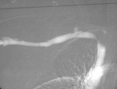 This carbon dioxide digital subtraction venogram shows stenosis of the right subclavian vein.
There are no absolute contraindications to the use of CO2 in upper-extremity venography. Relative contraindications include severe emphysema, pulmonary hypertension, and known intracardiac septal defects or pulmonary arteriovenous malformations. Initially, small amounts of CO2 (20 cc) should be used, so as to evaluate the effect of CO2 on the vital signs.
The injection of CO2 with the patient in the left lateral decubitus position facilitates the trapping of gas in the right atrium, thus preventing passage of the gas into the pulmonary arteries. Once CO2 is injected into a vein, the gas rapidly passes through the central veins and right cardiac chambers into the pulmonary arteries. The gas trapped in the pulmonary artery is absorbed within 15 to 30 seconds in the absence of air contamination (see the image below).
 Carbon dioxide trapped in the pulmonary artery (arrow) following the intravenous injection (A). The trapped gas has dissolved within 30 seconds (B)
The intravenous injection of CO2 in diagnostic doses (20 to 40 cc) has no effect on vital signs. If the systolic blood pressure drops from the baseline value by 10 to 20 mm Hg, air contamination should be suspected, and the delivery system should be checked for a potential source of air contamination. CO2 injections should be administered at intervals of 2 to 3 minutes to allow complete absorption of the gas.
CO2 wedged hepatic venography and manometry are important in the workup of patients with cirrhosis and portal hypertension, ascites of unknown etiology, hepatic venous outflow obstruction, suspected portal vein occlusion, and TIPS; it is also important for patients who require transjugular liver biopsy (see the images below).
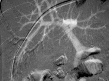 This carbon dioxide digital subtraction angiogram was obtained with an injection of carbon dioxide into the wedged hepatic venous catheter. Both the intrahepatic and extrahepatic portal veins fill nicely.
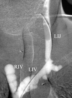 This carbon dioxide venogram of the left jugular vein (LIJ) was taken during parathyroid venous sampling for the localization of the source of parathyroid hormone excess. Left innominate (LI) and right innominate veins are visualized.
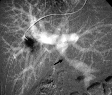 Carbon dioxide wedged hepatic venogram demonstrates stenosis of the portal vein (arrow).
A 5-Fr diagnostic catheter is wedged into a peripheral hepatic vein, using either the jugular vein or femoral vein approach. An occlusion balloon catheter may also be used to occlude the hepatic vein. CO2 is injected at a dose of 30 to 40 cc into a wedged hepatic vein to allow visualization of the intrahepatic and extrahepatic portal veins. In the absence of presinusoidal obstruction, the portal vein will also be visualized, regardless of the direction of the intrahepatic portal blood flow.
Wedged hepatic venography with iodinated contrast medium is used to determine the intrahepatic portal hemodynamics and to assess the morphology of the liver. The success rate of portal vein visualization with CO2 wedged hepatic venography is approximately 90%. For a TIPS procedure, more than 1 injection may be required to fill the central portal vein before portal vein puncture.
If CO2 wedged hepatic injections fail to show the portal vein, CO2 is injected into the parenchyma using a 21-gauge needle. We have performed wedged hepatic venography with CO2 and contrast medium in hundreds of patients. On several occasions, extravasation of CO2 into the subcapsular space and peritoneal cavity has occurred. In one of these cases, transfusion was required because of bleeding. The combination of CO2 wedged hepatic venography, hepatic manometry, and transjugular liver biopsy may provide the diagnostic information necessary for instituting appropriate therapy for patients with hepatic dysfunction.
CO2 is a safe and effective contrast agent for inferior vena cavography in patients with contrast allergy and renal failure (see the image below). CO2 angiography may provide accurate measurement of vena caval diameter and vascular road mapping before filter placement and vena caval interventions.
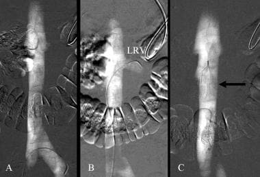 Carbon dioxide guided filter placement. A. CO2 inferior vena cavogram. B. Left renal venogram with CO2 (LRV). C. Inferior vena cavogram after deployment of a G2 filter (arrow).
We use the plastic bag delivery system for the CO2 injection for vena cavography. The technique used for CO2 venography before filter placement is as follows: a 5-Fr Cobra catheter is introduced from the right femoral vein and is advanced into the contralateral iliac vein for CO2 vena cavography to exclude the presence of a left-sided inferior vena cava. If reflux of CO2 into the left renal vein has not occurred, the catheter is advanced into the left renal vein for a CO2 renal venogram.
The catheter is also used to catheterize a retroaortic left renal vein. A filter is then deployed in the inferior vena cava below the lowest renal vein. If caval duplication is present, the filter is placed above the renal veins. CO2 may demonstrate nonocclusive caval thrombus, stenosis, and occlusion. CO2 may also be used as a contrast agent in the recanalization procedure of the occluded vena cava. Vital signs should remain stable following a bolus injection of CO2 in amounts of 30 to 40 cc. CO2 should be used with caution in patients with pulmonary insufficiency, pulmonary hypertension, and known intracardiac septal defects.
Splenoportography with contrast medium has been largely replaced by noninvasive imaging modalities (CTA and MRV) and arterial portography (also called indirect portography) (see the images below). Because of the low viscosity of CO2, diagnostic quantities (15 to 30 cc of CO2) of the gas may be injected into the splenic parenchyma, using a 22- to 25-gauge needle. Both in animals and in patients, the intrasplenic injections of CO2 cause no splenic laceration or hematoma. The splenic and portal veins are well visualized with CO2. This technique is particularly useful in pediatric patients for whom imaging studies of portal vein patency are inconclusive; it eliminates the need for femoral artery catheterization for arterial portography.
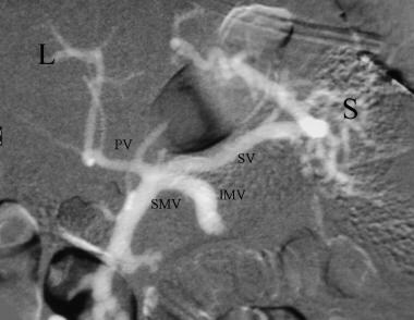 Splenoportogram with the injection of CO2 into the spleen (S) using a 22 gauge needle shows patent splenic (SV) and diminutive portal vein (PV). There is retrograde filling of the inferior mesenteric (IMV) and superior mesenteric (SMV) veins. L = liver
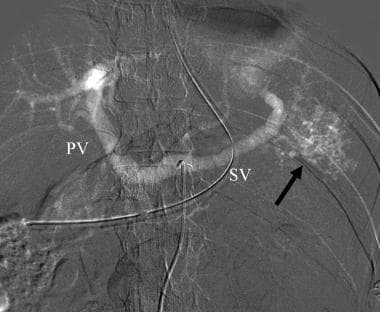 Carbon dioxide celiac angiogram in a patient with splenic injury demonstrates multiple small areas of gas collection in the spleen (arrow) and filling of the splenic (SV) and portal (PV) veins through intrasplenic arteriovenous fistula.
TIPS is a well accepted means of treating patients with variceal bleeding that is unresponsive to sclerotherapy; it is also used in cases of intractable ascites and cirrhotic hydrothorax. After the right or left internal jugular vein is accessed, a 10-Fr sheath is introduced. Pressure is measured in the right atrium and the inferior vena cava. A 5-Fr Cobra catheter or a curved-tipped catheter is advanced into the right hepatic vein to measure the free hepatic vein pressure.
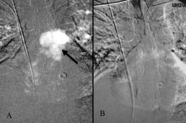
A CO2 hepatic venogram is then performed with the injection of 10 to 15 cc of CO2 using DSA imaging of the hepatic vein and pulmonary artery. The CO2 trapped in the central pulmonary artery dissolves within 30 seconds after the injection. Persistence of the gas bubble over 30 seconds suggests air contamination; in such cases, the procedure should be aborted and the plastic bag system should be checked for any source of air contamination (see the image below). Vital signs should be monitored, and the blood pressure should be checked 1 minute after the initial CO2 injection.
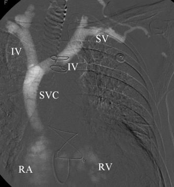 Left upper extremity venogram with CO2 nicely fills the subclavian (SV), innominate (IV), and superior vena cava (SVC). CO2 bubbles are seen in the right atrium (RA) and right ventricle (LV).
The catheter is then advanced until it becomes wedged. Once the catheter is wedged, the injection of 1 to 2 cc of contrast medium produces a sinusoidal blush; the wedged hepatic vein pressure is then measured. A CO2 wedged hepatic venogram is performed with the injection of 30 to 40 cc of CO2 and is imaged using the DSA technique.
After measuring portal vein pressure, a CO2 splenoportogram is performed with the injection of 30 to 40 cc of CO2. At this time, 20 cc of CO2 or 10 cc of contrast medium is injected into the hepatic parenchymal tract and imaged with the DSA technique to rule out transgression of the hepatic artery or bile duct. CO2 may be injected through the sheath to accurately deploy the stent from the portal vein through the parenchyma to the central hepatic vein.
If repeat pressure measurement reveals a gradient of less than 12 mm Hg between the right atrium and the portal vein, a completion digital subtraction portogram is obtained with the injection of 30 cc of CO2.
In the CO2 fine-needle TIPS procedure, the right or middle hepatic vein is catheterized with a 5-Fr Cobra catheter; 20 cc of CO2 is then injected using the plastic bag system. The hepatic vein and the pulmonary artery are then imaged with DSA. The CO2 trapped in the pulmonary artery usually dissolves within 30 seconds in the absence of air contamination.
The 21-gauge needle is then advanced from the central hepatic vein toward the portal vein, and 20 cc of CO2 is injected through the 21-gauge needle, using the plastic bag system in the anteroposterior projection. A repeat injection is made in the left anterior oblique projection to demonstrate the position of the needle in relation to the target portal vein.
Once the 0.018-inch guidewire is advanced toward the portal vein, CO2 is injected between the guide wire and the needle to confirm the position of the wire in the portal vein. Once the portal vein has been catheterized, the subsequent procedural steps for CO2 administration are the same as with the large-needle TIPS procedure.
Adverse Effects and Management
The occurrence and severity of the adverse effects of angiography may be related to the dose or to air contamination.
CO2 aortography and celiac arteriography may cause nausea and pain lasting 2-3 minutes. No specific treatment is required. Placing the patient in a left- or right-side-up position may relieve the pain. A decrease in the doses of CO2 usually reduces the frequency and severity of pain.
The injection of CO2 for runoff of the lower extremities may cause pain. Decreasing the amount of CO2 with selective injection and stacking technique helps reduce the pain.
The injection of CO2 into a peripheral vein for upper-extremity venography may cause pain at the injection site. The mechanism of pain is probably the explosive delivery secondary to gas compression. Purging the injection tube with 3 cc of CO2 and administering 20-40 mg of lidocaine immediately before the injection of CO2 for venous imaging helps reduce the pain.
Automated CO2 systems that deliver the CO2 gas at reduced pressure and a controlled manner, without the sudden release of CO2 gas, are being investigated. Preliminary studies report these systems are technically feasible and are safe and well tolerated by paitients. [32]
When CO2 is trapped in an aortic aneurysm, the gas bubbles may occlude the inferior mesenteric artery, resulting in colonic ischemia.
Inadvertent injection of excessive volumes of CO2 or air contamination may cause a vapor lock in the pulmonary artery, which results in severe hypotension. When air contamination occurs, fluoroscopy of the chest shows gas bubbles in the pulmonary artery that persists for longer than 30 seconds. If hypotension develops, the patient should be placed in the Trendelenburg and left lateral decubitus positions. If possible, air should be aspirated from the pulmonary artery using a catheter. [33, 34]
CO2 should not be used as an arterial contrast agent in sites above the diaphragm because of the risk of gas embolism of the spinal, coronary, and cerebral arteries. CO2 may be delivered by the hand-held syringe method, by the plastic bag system, or by the CO2mmander and AngiAssist. These delivery systems are safe if used correctly. Because air is poorly soluble, air contamination must be prevented during the delivery of CO2. Thorough understanding of the physical properties of CO2 and facile catheterization technique are essential in obtaining optimal CO2 imaging for both diagnosis and intervention. [6, 7, 8, 9, 10, 11, 12, 13, 14]
-
The plastic bag is connected to the carbon dioxide cylinder through a 0.2 micrometer filter. The 3-way stopcock between the cylinder and the bag allows filling and emptying of the bag with carbon dioxide to remove residual air from the bag.
-
Plastic bag and delivery system (Custom Waste Bag and Contrast Delivery Set, Merit Medical Systems, Inc. South Jordan, Utah). The bag is connected to the connecting tube where the injection syringe is located. The 3-way stopcock just distal to the check valve permits flushing and the injection of contrast medium into the catheter.
-
The CO2mannder (PMDA, LLCk, Ft. Myers, Fla) is an FDA-approved portable medical CO2 delivery system, allowing gas delivery at a low pressure through the AngiAssist. The unique stopcock system with valves controlling the direction of gas flow with the use of a 60-cc reservoir syringe and a 30-cc injection syringe allow safe delivery of CO2 in a nonexplosive fashion.
-
This frontal carbon dioxide digital subtraction aortogram shows a single right renal artery with a mild stenosis at the origin and 2 left renal arteries. The celiac and superior mesenteric arteries fill nicely because of their anterior origin.
-
This carbon dioxide digital subtraction angiogram shows patency of the external iliac and transplanted renal arteries.
-
This carbon dioxide digital subtraction angiogram (stacked image) of the left lower extremity shows the popliteal, anterior tibial, peroneal, and posterior tibial arteries.
-
This mesenteric carbon dioxide digital subtraction angiogram in a patient with small-bowel bleeding shows extravasation of carbon dioxide gas bubbles. Embolization with coils stopped the bleeding.
-
This carbon dioxide digital subtraction venogram shows stenosis of the right subclavian vein.
-
This carbon dioxide digital subtraction angiogram was obtained with an injection of carbon dioxide into the wedged hepatic venous catheter. Both the intrahepatic and extrahepatic portal veins fill nicely.
-
This carbon dioxide digital subtraction arteriogram in a patient with occlusion of the aorta (longer arrow) and both common iliac arteries (shorter arrows) was obtained with the injection of 30 cc of CO2 in the left external iliac artery using a 3F dilator. Because of the low viscosity, the gas flows well through the collaterals to the aorta and contralateral iliac arteries.
-
Carbon dioxide guided stent placement of right renal artery stenosis. A. CO2 DSA demonstrates orificeal stenosis of right renal artery (arrow). B. DSA with the injection of CO2 through the sheath demonstrates the stent in good position (arrow). C. After stent deployment, the renal artery is widely patent.
-
CO2 aortogram (cross-table lateral DSA) demonstrates narrowing of the celiac axis with concave impression (arrow) secondary to median arcuate ligament compression.
-
Celiac stenosis caused by median arcuate ligament compression. CO2 superior mesenteric DSA demonstrates filling of the gastroduodenal (GDA), common hepatic (CHA), and splenic (SA) arteries from the superior mesenteric artery (arrow).
-
CO2 celiac DSA. CO2 refluxes from the celiac axis back into the aorta, filling the superior mesenteric and bilateral renal arteries (RRA and LRA). The gastroduodenal (GDA), common hepatic (HA), splenic (SA), left gastric (LGA) and replaced left hepatic (LHA) arteries are visualized.
-
CO2 aortogram demonstrates celicomesenteric trunk, common origin of the celiac axis (CA) and superior mesenteric arteries. Common hepatic (HA) and splenic (SA) arteries are visualized.
-
This carbon dioxide aortogram obtained with the injection of CO2 through the sheath during endovascular aortic repair demonstrates the right (RRA) and left (LRA) renal arteries. AAA=abdominal aortic aneurysm
-
CO2 celiac angiogram in a patient with gastrointestinal bleeding following hepatic tumor resection shows a large pseudoaneurysm (arrow) arising from the distal celiac axis. Embolization controlled the bleeding
-
Right hepatic DSA with CO2 demonstrates a vascular tumor in the right hepatic lobe (arrow). The shorter arrow points at the tip of the microcatheter passed coaxially through the 5-Fr catheter positioned in the celiac axis. CO2 refluxed, filling the left hepatic and common hepatic arteries.
-
Carbon dioxide trapped in the pulmonary artery (arrow) following the intravenous injection (A). The trapped gas has dissolved within 30 seconds (B)
-
This carbon dioxide venogram of the left jugular vein (LIJ) was taken during parathyroid venous sampling for the localization of the source of parathyroid hormone excess. Left innominate (LI) and right innominate veins are visualized.
-
Carbon dioxide wedged hepatic venogram demonstrates stenosis of the portal vein (arrow).
-
Carbon dioxide guided filter placement. A. CO2 inferior vena cavogram. B. Left renal venogram with CO2 (LRV). C. Inferior vena cavogram after deployment of a G2 filter (arrow).
-
Left upper extremity venogram with CO2 nicely fills the subclavian (SV), innominate (IV), and superior vena cava (SVC). CO2 bubbles are seen in the right atrium (RA) and right ventricle (LV).
-
Splenoportogram with the injection of CO2 into the spleen (S) using a 22 gauge needle shows patent splenic (SV) and diminutive portal vein (PV). There is retrograde filling of the inferior mesenteric (IMV) and superior mesenteric (SMV) veins. L = liver
-
Carbon dioxide celiac angiogram in a patient with splenic injury demonstrates multiple small areas of gas collection in the spleen (arrow) and filling of the splenic (SV) and portal (PV) veins through intrasplenic arteriovenous fistula.