Practice Essentials
Fractures of the talus (see the images below) can be divided into types based on the 3 main anatomic divisions of the talus: body, neck, and head. Fractures of the body of the talus are further subdivided based on whether they traverse the main portion of the body or are fractures involving the talar dome, lateral process, or posterior process. Mechanisms of injury, treatment, and prognosis of the different types of talar fractures are markedly dissimilar.
Preferred examination
Plain radiographs of the foot and ankle are used to diagnose fractures of the talus. The views obtained depend on the particular fracture. Computed tomography (CT) scanning is used to evaluate displacement and to plan surgery. CT scanning and magnetic resonance imaging (MRI) are used to diagnose clinically occult fractures. A close, directed scrutiny of radiographs is needed to detect many talar fractures. Fractures of the lateral process are especially difficult; they may be visible on the anteroposterior (AP) ankle radiograph, the Broden view (45° internal oblique), or only on the lateral view of the foot.
CT scanning and MRI are used to detect radiographically occult fractures of the talus but must be performed with high resolution and attention to patient positioning. MRI can be difficult to interpret if planes orthogonal to the long axis of the talus are not used. CT scanning should be performed in the coronal and axial planes; otherwise, fractures may be missed. [1, 2, 3, 4, 5, 6]
Many talar fractures are subtle and easily missed; however, they can lead to long-term disability when there is a disruption of the subtalar or talonavicular joints. In a patient with a history of ankle injury, careful radiographic scrutiny should be given to the talar neck, head, and lateral process. The amount of joint involvement should be estimated because this is an important prognostic factor and influences treatment. CT scanning should be recommended if the radiologist is unsure of the extent of the fracture or to guide surgical intervention. [7]
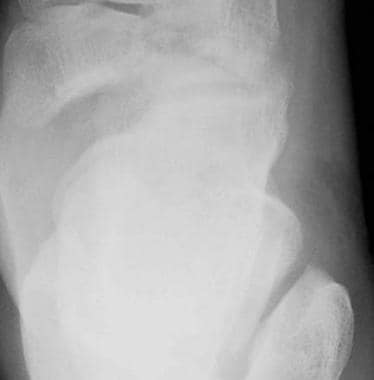
 Talar body fracture, anteroposterior radiograph. There is a sagittally oriented fracture through the body of the talus and disruption of the tibiotalar and subtalar joints. The injury was from a motor vehicle accident.
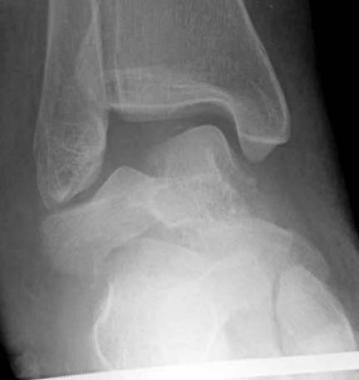
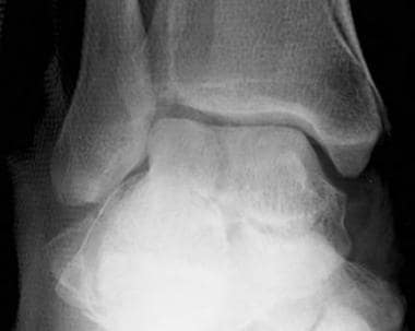
 Lateral process fracture, anteroposterior radiograph. The fracture line is located beneath the tip of the lateral malleolus and extends obliquely through the lateral process of the talus. LM=lateral malleolus, LP=lateral process of talus
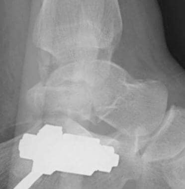
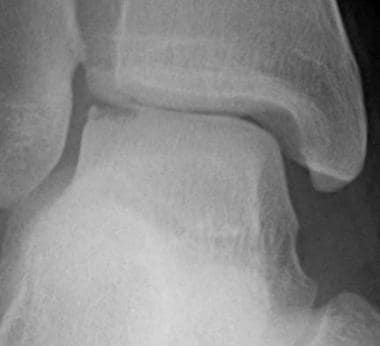
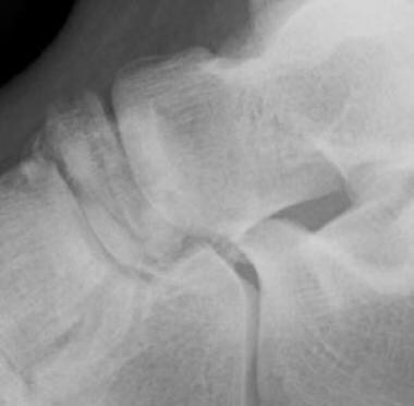
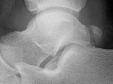 Posterior process fracture, lateral radiograph. The fracture is acute, which means that there is an absence of cortex around the posterior process fragment, clearly differentiating this from an os trigonum. Note also the ankle joint effusion and soft-tissue swelling adjacent to the fracture site.
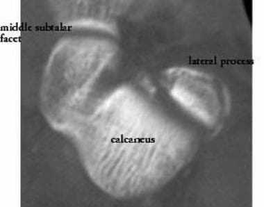
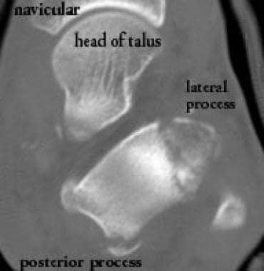 Fractures of the lateral and posterior processes of the talus, axial computed tomography (CT) scan. These fractures were associated with a talar body fracture.
Anatomy
The talus is unique in that no tendons attach to it. It is held in place by ligamentous and bony structures. The talus articulates superiorly with the tibia, medially and laterally with the medial and lateral malleoli (respectively), inferiorly with the calcaneus, and anteriorly with the navicular.
The body, which is the largest portion of the talus, is divided into 4 parts, as follows:
-
Dome - The dome articulates with the tibial plafond. Although termed a dome, it is shaped like a pulley, being convex from front to back but slightly concave from medial to lateral. Plantarflexion and dorsiflexion take place at the tibiotalar joint.
-
Central portion - The central portion has articular facets medially and laterally that articulate with the malleoli, as well as an inferior articular facet that articulates with the posterior facet of the calcaneus. Inversion and eversion, as well as plantarflexion and dorsiflexion, take place at the posterior subtalar joint.
-
Posterior process - The posterior process of the talus projects from the posteroinferior aspect of the talar body and is nonarticular. The flexor hallucis longus (FHL) tendon courses between medial and lateral tubercles of the posterior process. Fractures of the posterior process can affect the FHL. The posterior process of the talus can be present as a separate ossicle, the os trigonum.
-
Lateral process - The lateral process of the talus protrudes beneath the tip of the fibula. On a lateral radiograph, it forms a wedge shape at the anterior aspect of the posterior subtalar joint, with the apex of the wedge pointing inferiorly. The posterior subtalar facet extends into this region, and fractures of the lateral process often involve that joint.
The neck of the talus is roughly cylindrical in shape and is considerably narrower than the body. The talar neck is separated from the calcaneus by the fat-filled sinus tarsi.
The main blood supply of the talar body enters the talar neck from the sinus tarsi (a fat-filled space between the talar neck and the calcaneus) and proceeds retrograde to supply the talar body. Thus, fractures of the talar neck can compromise the vascularity of the body of the talus.
The head of the talus is convex anteriorly and articulates with the navicular. Abduction and adduction are the primary motions at the talonavicular joint.
Complications
Fractures of the talus can lead to avascular necrosis (AVN), arthritis, and, when unrecognized, chronic pain and nonunion. AVN of the body of the talus develops primarily after a displaced fracture of the talar neck—which disrupts the blood supply to the talar body—has occurred. The risk of AVN can be estimated by the Hawkins classification. An adequate blood supply to the talus can be inferred when a Hawkins sign is present (see the image below). [8]
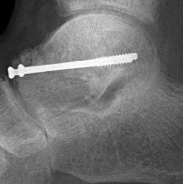
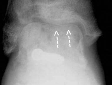 Partial Hawkins sign, anteroposterior radiograph. Following open reduction and internal fixation of a Hawkins type II fracture, a Hawkins sign (arrows), indicating intact vascularity, is seen over most of the talar dome. Laterally, however, the Hawkins sign is absent. The lateral portion of the dome is sclerotic, representing a small focus of avascular necrosis that has developed there.
Arthritis is a common complication following talar fracture. Talus-related arthritis can involve the tibiotalar, subtalar, or talonavicular joints. Exact surgical reduction is a goal in the prevention of posttraumatic arthritis.
Chronic pain and nonunion are not infrequent following undetected talar fractures. Osteochondral fractures of the talar dome, posterior process fractures, and lateral process fractures may be difficult to detect radiographically; clinically, they may be mistaken for ankle sprain. Patients with an undetected talar fracture present later with chronic pain and often with nonunion of the lateral or posterior process, at which time the fragment may require excision. Undetected osteochondral fractures may progress to loose bodies within the joint.
Ottawa Ankle Rules for Ankle Injury Radiography
The Ottawa Ankle Rules are simple guidelines developed to aid emergency physicians in deciding when to use radiography for patients with injuries to the ankle. The Ottawa Ankle Rules were developed and clinically tested to show that they led to a decrease in the use of ankle radiography, waiting times, and costs without patient dissatisfaction or missed fractures. [9]
An ankle x-ray series is only required if there is any pain in the malleolar zone and any of these findings:
-
Bone tenderness at the posterior edge or tip of the lateral malleolus
-
Bone tenderness at the posterior edge or tip of the medial malleolus
-
Inability to take 4 complete steps both immediately and in the ED
A foot x-ray series is only required if there is any pain in the midfoot zone and any of these findings:
-
Bone tenderness at the base of the 5th metatarsal
-
Bone tenderness at the navicular
-
Inability to take 4 complete steps both immediately and in the ED
Apply the Ottawa Ankle Rules accurately by doing the following:
-
Palpate the entire distal 6 cm of the fibula and tibia
-
Do not neglect the importance of medial malleolar tenderness
-
Do not use for patients younger than 18 years
Clinical judgment should prevail over the rules in the following circumstances:
-
If the patient is intoxicated or uncooperative
-
If the patient has other distracting painful injuries
-
If the patient has diminished sensation in the legs
-
If the patient has gross swelling that prevents palpation of malleolar bone tenderness
Give written instructions and encourage follow-up in 5-7 days if pain and ability to walk are not better.
(see Ottawa Ankle Rule for the Use of X-Ray in Ankle Injury).
American College of Radiology (ACR) Appropriateness Criteria
ACR Appropriateness Criteria for acute trauma to the ankle includes the following [10] :
-
The use of 3-view (anteroposterior, lateral, and mortise) radiographic evaluation of patients meeting the criteria of the Ottawa ankle rules.
-
Cross-sectional imaging has a limited secondary role primarily as a tool for preoperative planning and as a problem-solving technique in patients with persistent symptoms and suspected of having occult fractures.
ACR Appropriateness Criteria for chronic ankle pain includes the following [11] :
-
Radiograph of the ankle is the most appropriate initial imaging study.
-
MRI ankle without IV contrast should be ordered as the next study after radiographs when there is pain of uncertain etiology and ankle radiographs are normal.
For patient education see the Breaks, Fractures, and Dislocations Center, as well as Ankle Fracture and Broken Foot.
Radiography
Plain radiographic imaging of the foot and ankle are used to diagnose fractures of the talus. The views obtained depend on the particular fracture.
A close, directed scrutiny of radiographs is needed to detect many talar fractures. Fractures of the lateral process are especially difficult; they may be visible on the anteroposterior (AP) ankle radiograph, the Broden view (45° internal oblique), or only on the lateral view of the foot.
(See the radiographic images below displaying talar fractures.)
Talar body fracture, anteroposterior radiograph. There is a sagittally oriented fracture through the body of the talus and disruption of the tibiotalar and subtalar joints. The injury was from a motor vehicle accident.
 Talar body fracture, lateral radiograph (same patient as in the previous image). There is a significant degree of comminution of the talar fracture, with comminuted fracture lines extending into the posterior and lateral processes of the talus.
 Talar body fracture, anteroposterior radiograph. This patient had a fall resulting in a pilon fracture of the tibia, a sagittally oriented fracture of the body of the talus, and a central compressive fracture of the calcaneus.
 Talar body fracture, lateral radiograph (same patient as in the previous image). The fracture of the talus, existing purely in the sagittal plane, is not visible on the lateral radiograph. However, the central compressive calcaneal fracture is well visualized.
Lateral process fracture, anteroposterior radiograph. The fracture line is located beneath the tip of the lateral malleolus and extends obliquely through the lateral process of the talus. LM=lateral malleolus, LP=lateral process of talus
Talar body fracture, lateral radiograph (same patient as in the previous image). The fracture of the talus, existing purely in the sagittal plane, is not visible on the lateral radiograph. However, the central compressive calcaneal fracture is well visualized.
Lateral process fracture, anteroposterior radiograph. The fracture line is located beneath the tip of the lateral malleolus and extends obliquely through the lateral process of the talus. LM=lateral malleolus, LP=lateral process of talus
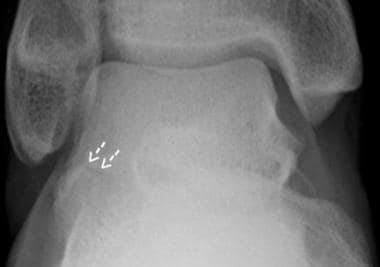 Patient OA. Lateral process of talus fracture, anteroposterior radiograph. The fracture line (arrows) is nondisplaced and medially located at the junction of the lateral process and central body of the talus, making it difficult to see.
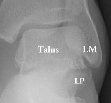
 Patient OA. Lateral process of talus fracture, lateral radiograph. The fracture line is better appreciated on this image, which isolates a triangular fragment at the tip of the lateral process of the talus.
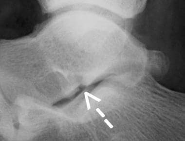
Posterior process fracture, lateral radiograph. The fracture is acute, which means that there is an absence of cortex around the posterior process fragment, clearly differentiating this from an os trigonum. Note also the ankle joint effusion and soft-tissue swelling adjacent to the fracture site.
Patient OA. Lateral process of talus fracture, lateral radiograph. The fracture line is better appreciated on this image, which isolates a triangular fragment at the tip of the lateral process of the talus.
Posterior process fracture, lateral radiograph. The fracture is acute, which means that there is an absence of cortex around the posterior process fragment, clearly differentiating this from an os trigonum. Note also the ankle joint effusion and soft-tissue swelling adjacent to the fracture site.
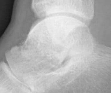
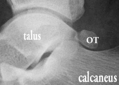 Os trigonum (OT), lateral radiograph. The ossicle is shaped like a smooth pebble and is well corticated.
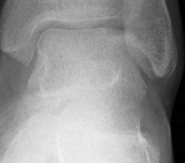 Stage 2A osteochondral fracture of the lateral talar dome, anteroposterior radiograph. There is a semicircular subcortical lucency at the lateral aspect of the talar dome, and a slight cortical depression is present.
 Stage 4 osteochondral fracture of the talar dome, mortise radiograph. A small cortical fragment has become dislodged, leaving a small bony defect at the most lateral aspect of the talar dome.
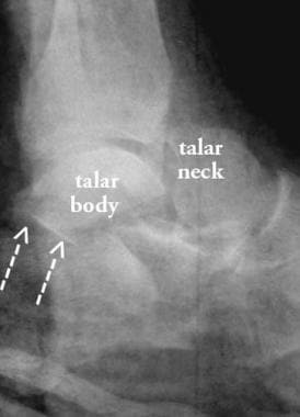
 Hawkins type I fracture of the talar neck, lateral radiograph. These fractures are quite subtle. Disruption of the dorsal cortex of the talar neck is visible, and the fracture line can be faintly followed vertically through the talar neck. Computed tomography (CT) scanning is useful to confirm the fracture.
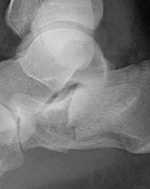
 Hawkins type III fracture of the talar neck, lateral radiograph. The fracture of the talar neck is completely displaced dorsally. The posterior subtalar joint is dislocated, and the articular facet of the talus (arrows) is seen lying behind the articular facet of the calcaneus. The tibiotalar joint is subluxed.
 Avascular necrosis (AVN) of the talar body, lateral radiograph. The entire talar dome is sclerotic because of AVN, which occurred as a complication of a talar neck fracture.
Partial Hawkins sign, anteroposterior radiograph. Following open reduction and internal fixation of a Hawkins type II fracture, a Hawkins sign (arrows), indicating intact vascularity, is seen over most of the talar dome. Laterally, however, the Hawkins sign is absent. The lateral portion of the dome is sclerotic, representing a small focus of avascular necrosis that has developed there.
Avascular necrosis (AVN) of the talar body, lateral radiograph. The entire talar dome is sclerotic because of AVN, which occurred as a complication of a talar neck fracture.
Partial Hawkins sign, anteroposterior radiograph. Following open reduction and internal fixation of a Hawkins type II fracture, a Hawkins sign (arrows), indicating intact vascularity, is seen over most of the talar dome. Laterally, however, the Hawkins sign is absent. The lateral portion of the dome is sclerotic, representing a small focus of avascular necrosis that has developed there.
 Medial fracture dislocation of the talonavicular joint, anteroposterior (AP) radiograph. On the AP radiograph, the medial dislocation of the talonavicular joint is evident. More difficult to see is the oblique fracture through the head of the talus.
Talar body fractures
The mechanism of injury for talar body fracture is axial load or shear. Associated injuries include those to the calcaneus, tibia, talar neck.
Radiographic assessment consists of AP, mortise (15° internal oblique), lateral, and Broden views (it is important to quantify the degree of articular involvement and displacement). Displacement of articular facet of posterior subtalar joint necessitates the Broden view or a CT scan. For advanced imaging, a CT scan in the coronal plane (defined as coronal relative to the tibia) is used to assess comminution, articular disruption, and associated fractures.
Treatment consists of open reduction and internal fixation (ORIF), and complications include a high incidence of subtalar arthritis.
Osteochondral fractures of the talar dome
The terms osteochondral fracture, transchondral fracture, and osteochondritis dissecans (OCD) are used interchangeably in the region. However, the first 2 terms are preferable because the fracture is caused by a single episode of trauma. These fractures are most commonly classified by the system devised by Berndt and Harty (see Table 1, below), which has been modified to include MRI findings.
Table 1. Classification of Osteochondral Fractures of the Talar Dome (Open Table in a new window)
Stage |
Radiographs |
MRI T2WI * |
Arthroscopy |
1 |
Normal |
Diffuse, high-signal intensity |
Normal, or softening of cartilage |
2 |
Semicircular lucent line |
Semicircular, low-signal line |
Break in cartilage; fragment, no displacement |
2a** |
Subcortical round lucency |
High-signal fluid within fragment |
|
3 |
Same as 2 |
High-signal fluid surrounds fragment |
Displaceable fragment |
4 |
Loose body |
Defect talar dome, possibly loose body |
Defect plus loose body |
*T2WI= T2-weighted imaging **Stage 2a is a variant in which a cyst forms in the subcortical bone |
|||
Characteristics of fractures of the talar dome include the following:
-
Mechanism of injury - Inversion injury of the ankle; a lateral osteochondral fracture results from shearing of a small fragment of cartilage and bone; compression of the talar dome causes medial fracture
-
Associated injuries - These include tears of the lateral collateral ligament of the ankle
-
Location - Injury occurs in the lateral or medial aspect of the talar dome
-
Radiographic assessment - AP and mortise views. Sensitivity is increased if the mortise view is performed in plantarflexion and dorsiflexion
-
Advanced imaging - MRI to evaluate cartilage and the presence of a loose fragment. CT arthrography also can be used.
-
Classification - The most commonly used classification is the Berndt and Harty system (containing later modifications to incorporate MRI findings)
-
Treatment - Drilling may be performed in the early stages to promote healing; large fragments may be reattached or removed
-
Complications - Injury may lead to ankle arthritis and loose bodies
Posterior process fractures
Characteristics of posterior process fractures include the following:
-
Terminology - Occasionally known as Shepherd's fracture
-
Mechanism of injury - Hyperplantarflexion or avulsion of the posterior talofibular ligament; also, stress fracture in athletes and (especially) ballet dancers
-
Associated injuries - Talar body fracture, injury of FHL tendon (see Anatomy, above)
-
Radiographic assessment - Seen on lateral radiograph; must differentiate this injury from an os trigonum (a nonunited, accessory center of ossification of the posterior process)
-
Advanced imaging - Not needed (although posterior process fractures are readily seen on axial CT scans)
-
Treatment - Conservative; removal of fragment if there is painful nonunion
-
Complications - May result in chronic pain and nonunion
Lateral process fractures
Characteristics of lateral process fractures include the following:
-
Terminology - Also known as snowboarder's fracture
-
Mechanism of injury - Eversion injury; the lateral process is caught between the lateral malleolus of the fibula above it and the calcaneus below it; the injury may also be caused by inversion and dorsiflexion; it is increasing in incidence
-
Radiographic assessment - Mortise or Broden view; the fracture is vertically oriented, and the fragment varies in composition from a small flake of cortical bone to most of the lateral process; the degree of involvement of the subtalar joint should be assessed; the fracture may be radiographically occult
-
Advanced imaging - MRI or CT scanning are useful for occult fractures; these modalities can be used to assess the subtalar joint and evaluate for nonunion
-
Treatment - Nonarticular chip fractures are treated conservatively; articular fragments may be excised or treated with ORIF; there is a high incidence of nonunion and osteoarthritis of the subtalar joint
Talar neck fractures
The classification system created by Hawkins, as modified by Canale and Kelly, should be used (see Table 2, below). [12]
Table 2. Hawkins Classification of Talar Neck Fractures (Open Table in a new window)
|
Radiographic findings |
Risk of AVN |
Type I |
Nondisplaced fracture line |
0-13% |
Type II |
Displaced fracture, subluxation or dislocation of subtalar joint |
20-50% |
Type III |
Displaced fracture, dislocation of subtalar and tibiotalar joints |
69-100% |
Type IV |
Displaced fracture, disruption of talonavicular joint |
High |
There are 3 mechanisms of injury of talar neck fractures:
-
The most common mechanism is a dorsally directed force on a braced foot, such as that encountered in head-on motor vehicle accidents; talar neck fractures were once known as "aviator's astragalus," because World War I pilots suffered the fracture during plane crashes in which their foot was dorsiflexed on the floorboard of the plane
-
Another mechanism is inversion of the ankle, with impingement of the talar neck against the medial malleolus
-
A third mechanism is a direct blow to the dorsum of the foot
Radiographic assessment of talar neck fractures include the following:
-
A lateral radiograph of the foot should be employed; the injury is difficult to see on AP of the foot unless displacement has occurred; an angled view was described by Canale and Kelly but is difficult to perform
-
Follow-up radiographs should be evaluated for the presence of a Hawkins sign, a subcortical lucency that is caused by hyperemia and consequent bone resorption; if a Hawkins sign appears, this indicates that AVN will not develop
Other characteristics of talar neck fractures include the following:
-
Advanced imaging - CT scanning can be used to confirm the presence of a subtle fracture and to evaluate reduction
-
Complications - Since most of the blood supply to the talar body comes by way of the talar neck, fractures of the neck place the patient at risk of developing AVN
-
Treatment - ORIF is employed, with attention to precise anatomic reduction, especially of the articular surfaces
-
Complications - AVN and subtalar arthritis can occur
Talar head fractures
The following are characteristics of talar head fractures:
-
Mechanism of injury - Axial compression; can also occur secondary to talonavicular joint dislocation
-
Associated injuries - Other foot fractures, dislocation of the talonavicular joint
-
Radiographic assessment - AP and lateral radiographs of the foot (the fractures are usually obliquely oriented)
-
Advanced imaging - Not routinely indicated; may be useful to assess the talonavicular joint
-
Treatment - Reduction of joint, occasionally ORIF
Degree of confidence
Several fractures of the talus can be difficult to detect radiographically, including osteochondral fracture, lateral process fracture, and nondisplaced talar neck fracture. Whenever trauma radiographs of the foot or ankle are obtained, a high degree of attention should be paid to the areas where these subtle fractures occur.
If doubt exists as to the presence of a fracture, MRI is the test of choice. CT scanning also shows occult fractures, but unlike MRI, it cannot differentiate between stage II and stage III osteochondral fractures.
The os trigonum, an accessory center of ossification for the posterior process of the talus, must be differentiated from a posterior process fracture. The following criteria are used:
-
A fracture line is sharply angled relative to the remainder of the bone, while an accessory center of ossification tends to be shaped like a smooth pebble
-
The pieces of a fractured bone fit together precisely, like 2 pieces of a jigsaw puzzle, while an accessory ossicle usually does not fit tightly with the parent bone; CT scanning may occasionally be necessary to make this differentiation
-
An acute fracture line will not have a sclerotic margin, while an accessory ossicle is surrounded by dense, cortical bone
Computed Tomography
CT scanning is used to detect radiographically occult fractures of the talus but must be performed with high resolution and attention to patient positioning. CT scanning should be performed in the coronal and axial planes; otherwise, fractures may be missed. CT scan findings are integrated with plain radiographic findings for each type of fracture. [13, 14]
(See the CT images below displaying fractures of the talus.)
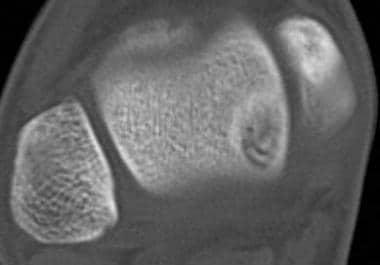
 Lateral process fracture. Axial computed tomography (CT) scan; the involvement of the subtalar joint is more easily seen on a CT scan.
Fractures of the lateral and posterior processes of the talus, axial computed tomography (CT) scan. These fractures were associated with a talar body fracture.
Lateral process fracture. Axial computed tomography (CT) scan; the involvement of the subtalar joint is more easily seen on a CT scan.
Fractures of the lateral and posterior processes of the talus, axial computed tomography (CT) scan. These fractures were associated with a talar body fracture.
 Axial computed tomography (CT) scan showing an osteochondral fracture lesion. On an axial image, the area of the osteochondral fracture is circular, and the density within it is heterogeneous.
Magnetic Resonance Imaging
If doubt exists as to the presence of a fracture, MRI is the test of choice. CT scanning also shows occult fractures, but unlike MRI, it cannot differentiate between stage II and stage III osteochondral fractures. MRI can be difficult to interpret if planes orthogonal to the long axis of the talus are not used. [5]
(Magnetic resonance images of talar fractures are provided below.)
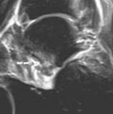 Patient OA. Lateral process fracture; sagittal, fast spin-echo, inversion recovery magnetic resonance image. The tip of the lateral process shows high signal intensity consistent with edema. The magnetic resonance imaging (MRI) scan was performed several months after the fracture, and the fracture line has partially healed.
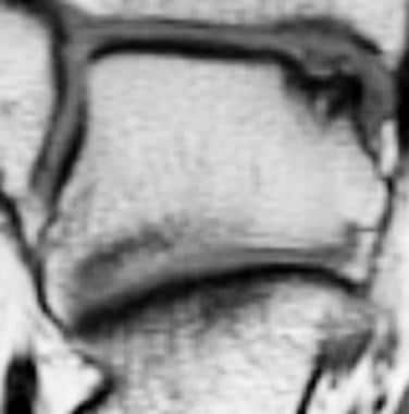 Patient BM. Coronal, T1-weighted magnetic resonance image of a stage 3 osteochondral fracture. A thin cortical fragment is seen; it is separated from the concave bony defect beneath it by intermediate–signal-intensity material. A stage 3 lesion is confirmed on T2-weighted and fast spin-echo, inversion recovery images.
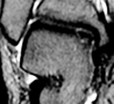 Patient BM. Coronal, fast spin-echo, T2-weighted magnetic resonance image with fat saturation, showing a stage 3 osteochondral fracture of the talar dome. A tiny cartilage defect is seen in the talar dome, showing the higher signal intensity of fluid compared to the intermediate signal intensity of cartilage. Fluid is also seen between the osteochondral fragment and adjacent bone, indicating that the fragment is detached but nondisplaced.
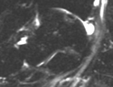 Patient BM. Sagittal, fast spin-echo, inversion recovery magnetic resonance image showing a stage 3 osteochondral fracture. On a fast spin-echo, inversion recovery image, the high–signal-intensity line around the osteochondral fragment is better seen.
Nuclear Imaging
Nuclear medicine imaging (see the image below) currently has little role in the evaluation of talus fractures. MRI has equal sensitivity to nuclear medicine imaging techniques but with much greater specificity. However, a bone scan performed to evaluate chronic pain will show uptake corresponding to the fracture site.
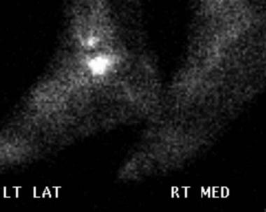 Patient OA. Lateral process of the talus fracture. Lateral view of technetium-99m (99mTc) bone scan at 5 hours following injection. The fracture site shows a markedly increased uptake of radionuclide.
SPECT/CT can detect osteochondral lesions, osteoarthritis, tarsal coalition, occult fractures, or painful accessory bones. SPECT/CT arthrography, the combination of CT arthrography and late-phase bone SPECT/CT, has been used in knee, ankle, and wrist joints. Compared with SPECT/CT alone, additional intra-articular contrast enables the assessment of cartilage, ligaments, and loose bodies. SPECT/CT arthrography is a promising alternative technique for the evaluation of internal derangement of joints in patients with MR contraindications and/or metallic implants. [15]
Guidelines
American College of Radiology (ACR) Appropriateness Criteria
ACR Appropriateness Criteria for acute trauma to the ankle includes the following [10] :
-
The use of 3-view (anteroposterior, lateral, and mortise) radiographic evaluation of patients meeting the criteria of the Ottawa ankle rules.
-
Cross-sectional imaging has a limited secondary role primarily as a tool for preoperative planning and as a problem-solving technique in patients with persistent symptoms and suspected of having occult fractures.
ACR Appropriateness Criteria for chronic ankle pain includes the following [11] :
-
Radiograph of the ankle is the most appropriate initial imaging study.
-
Ankle MRI without IV contrast should be ordered as the next study after radiographs when there is pain of uncertain etiology and ankle radiographs are normal.
(see Ottawa Ankle Rule for the Use of X-Ray in Ankle Injury).
-
Talar body fracture, anteroposterior radiograph. There is a sagittally oriented fracture through the body of the talus and disruption of the tibiotalar and subtalar joints. The injury was from a motor vehicle accident.
-
Talar body fracture, lateral radiograph (same patient as in the previous image). There is a significant degree of comminution of the talar fracture, with comminuted fracture lines extending into the posterior and lateral processes of the talus.
-
Talar body fracture (same patient as in the previous image). Coronal computed tomography (CT) scan through the posterior subtalar joint. There is wide separation of the talar fragments. The degree of the subtalar joint dislocation and the marked comminution of the medial portion of the talus are evident.
-
Talar body fracture, anteroposterior radiograph. This patient had a fall resulting in a pilon fracture of the tibia, a sagittally oriented fracture of the body of the talus, and a central compressive fracture of the calcaneus.
-
Talar body fracture, lateral radiograph (same patient as in the previous image). The fracture of the talus, existing purely in the sagittal plane, is not visible on the lateral radiograph. However, the central compressive calcaneal fracture is well visualized.
-
Lateral process fracture, anteroposterior radiograph. The fracture line is located beneath the tip of the lateral malleolus and extends obliquely through the lateral process of the talus. LM=lateral malleolus, LP=lateral process of talus
-
Lateral process fracture. Axial computed tomography (CT) scan; the involvement of the subtalar joint is more easily seen on a CT scan.
-
Patient OA. Lateral process of talus fracture, anteroposterior radiograph. The fracture line (arrows) is nondisplaced and medially located at the junction of the lateral process and central body of the talus, making it difficult to see.
-
Patient OA. Lateral process of talus fracture, lateral radiograph. The fracture line is better appreciated on this image, which isolates a triangular fragment at the tip of the lateral process of the talus.
-
Patient OA. Lateral process of the talus fracture. Lateral view of technetium-99m (99mTc) bone scan at 5 hours following injection. The fracture site shows a markedly increased uptake of radionuclide.
-
Patient OA. Lateral process fracture; sagittal, fast spin-echo, inversion recovery magnetic resonance image. The tip of the lateral process shows high signal intensity consistent with edema. The magnetic resonance imaging (MRI) scan was performed several months after the fracture, and the fracture line has partially healed.
-
Posterior process fracture, lateral radiograph. The fracture is acute, which means that there is an absence of cortex around the posterior process fragment, clearly differentiating this from an os trigonum. Note also the ankle joint effusion and soft-tissue swelling adjacent to the fracture site.
-
Os trigonum (OT), lateral radiograph. The ossicle is shaped like a smooth pebble and is well corticated.
-
Fractures of the lateral and posterior processes of the talus, axial computed tomography (CT) scan. These fractures were associated with a talar body fracture.
-
Stage 2A osteochondral fracture of the lateral talar dome, anteroposterior radiograph. There is a semicircular subcortical lucency at the lateral aspect of the talar dome, and a slight cortical depression is present.
-
Stage 4 osteochondral fracture of the talar dome, mortise radiograph. A small cortical fragment has become dislodged, leaving a small bony defect at the most lateral aspect of the talar dome.
-
Axial computed tomography (CT) scan showing an osteochondral fracture lesion. On an axial image, the area of the osteochondral fracture is circular, and the density within it is heterogeneous.
-
Patient BM. Coronal, T1-weighted magnetic resonance image of a stage 3 osteochondral fracture. A thin cortical fragment is seen; it is separated from the concave bony defect beneath it by intermediate–signal-intensity material. A stage 3 lesion is confirmed on T2-weighted and fast spin-echo, inversion recovery images.
-
Patient BM. Coronal, fast spin-echo, T2-weighted magnetic resonance image with fat saturation, showing a stage 3 osteochondral fracture of the talar dome. A tiny cartilage defect is seen in the talar dome, showing the higher signal intensity of fluid compared to the intermediate signal intensity of cartilage. Fluid is also seen between the osteochondral fragment and adjacent bone, indicating that the fragment is detached but nondisplaced.
-
Patient BM. Sagittal, fast spin-echo, inversion recovery magnetic resonance image showing a stage 3 osteochondral fracture. On a fast spin-echo, inversion recovery image, the high–signal-intensity line around the osteochondral fragment is better seen.
-
Hawkins type I fracture of the talar neck, lateral radiograph. These fractures are quite subtle. Disruption of the dorsal cortex of the talar neck is visible, and the fracture line can be faintly followed vertically through the talar neck. Computed tomography (CT) scanning is useful to confirm the fracture.
-
Hawkins type III fracture of the talar neck, lateral radiograph. The fracture of the talar neck is completely displaced dorsally. The posterior subtalar joint is dislocated, and the articular facet of the talus (arrows) is seen lying behind the articular facet of the calcaneus. The tibiotalar joint is subluxed.
-
Avascular necrosis (AVN) of the talar body, lateral radiograph. The entire talar dome is sclerotic because of AVN, which occurred as a complication of a talar neck fracture.
-
Partial Hawkins sign, anteroposterior radiograph. Following open reduction and internal fixation of a Hawkins type II fracture, a Hawkins sign (arrows), indicating intact vascularity, is seen over most of the talar dome. Laterally, however, the Hawkins sign is absent. The lateral portion of the dome is sclerotic, representing a small focus of avascular necrosis that has developed there.
-
Medial fracture dislocation of the talonavicular joint, anteroposterior (AP) radiograph. On the AP radiograph, the medial dislocation of the talonavicular joint is evident. More difficult to see is the oblique fracture through the head of the talus.
-
Lateral radiograph of a talonavicular fracture dislocation.
Tables
Stage |
Radiographs |
MRI T2WI * |
Arthroscopy |
1 |
Normal |
Diffuse, high-signal intensity |
Normal, or softening of cartilage |
2 |
Semicircular lucent line |
Semicircular, low-signal line |
Break in cartilage; fragment, no displacement |
2a** |
Subcortical round lucency |
High-signal fluid within fragment |
|
3 |
Same as 2 |
High-signal fluid surrounds fragment |
Displaceable fragment |
4 |
Loose body |
Defect talar dome, possibly loose body |
Defect plus loose body |
*T2WI= T2-weighted imaging **Stage 2a is a variant in which a cyst forms in the subcortical bone |
|||
|
Radiographic findings |
Risk of AVN |
Type I |
Nondisplaced fracture line |
0-13% |
Type II |
Displaced fracture, subluxation or dislocation of subtalar joint |
20-50% |
Type III |
Displaced fracture, dislocation of subtalar and tibiotalar joints |
69-100% |
Type IV |
Displaced fracture, disruption of talonavicular joint |
High |