Practice Essentials
The orbit is a conical structure, with its base facing anterolaterally and its apex originating medially as the inlet of all vital neural and vascular structures via the optic foramen, superior orbital fissure, and inferior orbital fissure. The anterior rim of the bony orbit, the orbital rim, is formed by orbital processes from the maxilla, zygoma, and frontal bone. [1, 2]
Orbital fractures may be defined in terms of anatomic considerations. Some fractures may be limited to the internal orbital skeleton, including blow-out and blow-in patterns, as seen in isolated fractures of the orbital floor, medial wall, and roof. Orbital blow-out fractures include trapdoor fractures, caused by low force; medial blow-out fractures, caused by intermediate force; and lateral blow-out fractures, caused by high force. [3]
Fractures may involve the orbital rim. An inferior, lateral, or superior rim fracture may be an isolated injury, or it may be contiguous with an internal-wall fracture. Fractures can also be associated with other fractures of the facial skeleton. Orbit involvement is seen in various facial fracture patterns, including zygomaticomaxillary (ZMC), [4] naso-orbito-ethmoid (NOE), frontal-sinus, Le Fort II, and Le Fort III fracture patterns.
Orbital apex fractures are important to identify because of their association with damage to the neurovascular structures of the superior orbital fissure and optic canal (including traumatic optic neuropathy).
Imaging modalities
Optimally, plain radiography of the orbit should include the acquisition of direct frontal (posteroanterior [PA] or anteroposterior [AP]), Caldwell, Waters, Towne, and lateral views. That is, views may include the following: side (lateral, from both sides), back to front (PA), and base views. Also, an image from the center to one outside edge (half-axial projection) and projections of the optical canal may be useful. For all of these views, the patient may be seated upright or lying down.
When clinical suspicion of orbital fracture persists but the plain radiographic findings are equivocal or unremarkable, CT scan study is required for a more definitive assessment of the orbits. CT scanning is the study of choice for orbital fractures, offering the highest degree of confidence. Thin-section coronal images provide an excellent depiction of all orbital walls, especially the floor and roof. CT scanning that employs a section thickness of 3 mm or less best illustrates fine bony structures of the midface and orbits. [5, 6]
In cases with minimal or no facial fracture symptoms, or when the patient is unable to undergo an ophthalmologic examination, orbital fractures can go undetected. A study by Huang et al suggests that maxillary hemosinus (MHS) findings on head CT scans may be used to screen for orbital floor fractures (OFFs). In the study, the absence of MHS had a negative predictive value (99.7%) for excluding OFF, while an MHS showing high-attenuation opacity mixed with mottled gas had a positive predictive value (69.5%). [7]
After the intraorbital presence of metal bodies has been excluded, preferably by means of CT scanning, MRI can be used for adjunct characterization of soft-tissue sequelae. As with CT scanning, MRI can demonstrate globe injuries, retrobulbar fluid collection (hematoma or other), subperiosteal hemorrhage, and hemorrhage along the optic nerve sheath, as well as the proximity of extraocular muscles to the fracture edges.
Ultrasonography is not generally applicable in the examination of orbital fractures. However, this imaging modality is used at major eye-trauma centers for evaluating intraocular structures. Ultrasonography requires a dedicated ophthalmologic technician and may not reveal important cranial injuries.
(See the images below.)
 The lateral wall of the orbit is formed by the frontal process of the zygomatic bone and the greater wing of the sphenoid bone.
Postacceleration injury, motor vehicle collisions, and violent crimes result in myriad orbital fractures and midfacial fractures. Along the visual pathways, trauma in these regions is divided into 4 major locations: intraocular, intraorbital, intracanalicular, and intracranial. The following discussion focuses on the patterns of orbital injury classified as blow-out or blow-in fractures (see the images below), with peripheral consideration of tripod and Le Fort fractures.
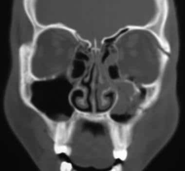
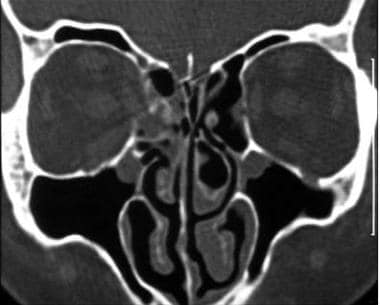 Coronal computed tomography scan shows a medial wall blow-out fracture of the right eye. Orbital fat is seen to herniate into the defect.
Le Fort classification
In 1901, Renée Le Fort provided the earliest classification system of maxillary fractures. His model described "great lines of weakness in the face" caused by low-velocity impact forces directed against cadaver skulls. [8]
The Le Fort I, or transverse, fracture extends through the base of the maxillary sinuses above the teeth apices, essentially separating the alveolar processes, palate, and pterygoid processes from the facial structures above them. This transverse fracture across the entire lower maxilla separates the alveolus as a mobile unit from the rest of the midface. Segments of the alveolus may be dislocated as a result of this fracture. High-energy injuries may cause a Le Fort I fracture and a split along the palate's midline.
A Le Fort II fracture, also termed a pyramidal fracture of the maxilla, begins laterally, similar to a Le Fort I fracture, but medially diverges in a superior direction to include part of the medial orbit as well as the nose (see the image below). The fracture across the nose may be variable; in some cases it involves only the nasal cartilage, and in other, more extensive cases, the nasofrontal suture. The fracture extends diagonally from the pterygoid plates through the maxilla to the inferior orbital rim and up the medial wall of the orbit to the nose. This fracture separates the maxillary alveolus, medial wall of the orbit, and nose into separate pieces.
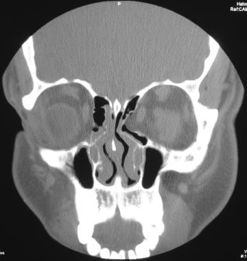
 Computed tomography scan showing bilateral fractures of the orbital floor associated with a Le Fort II injury.
A Le Fort III fracture, or craniofacial dysjunction, denotes a complete separation of the midface or facial bones from the cranium. This fracture traverses the zygomaticofrontal suture, continues through the floor of the orbit, and finally passes through the nasofrontal suture. The bones of the orbit are separated through the lateral wall, floor, and medial wall. This fracture rarely results in a single segment of bone; more commonly, the break is comminuted, making up any of a variety of combinations of zygomatic,nasoethmoid, and orbital fractures. The fractures on the 2 sides may not be symmetrical, and minimal mobility may be present. [1, 9, 10, 11, 12, 13]
Although still widely used, the Le Fort classification system was developed based on fractures caused by low-speed trauma to the face. However, today, midfacial and orbital fractures caused by high-speed trauma are predominant, which can result in naso-orbito-ethmoid fractures. These fractures are not well described using Le Fort classifications. Naso-orbito-ethmoid fractures can be classified on the basis of extent of injury to the attachment of the medial canthal tendon, with possible complications such as nasofrontal duct disruption. [14]
For clinical evaluation, the following are important:
-
Be familiar with the complex anatomy of the orbit and relative soft tissues, as displayed on computed tomography (CT) scans and magnetic resonance images (MRIs) in multiple planes.
-
Be able to identify common acute emergent lesions.
-
Be familiar with the plain radiographic and CT scan appearances of traumatic fractures of the orbit.
-
Be able to characterize fractures based on clinical classification systems (eg, Le Fort classification).
Radiography
Orbital radiography should include several views to clearly depict the various parts of the eye without obstruction. Images of the unaffected eye may also be obtained to compare its shapes and structures with those of the affected eye. (See the image below.)
Optimally, plain radiography of the orbit should include the acquisition of direct frontal (posteroanterior [PA] or anteroposterior [AP]), Caldwell, Waters, Towne, and lateral views. That is, views may include the following: side (lateral, from both sides), back to front (PA), and base views. Also, an image from the center to one outside edge (half-axial projection) and projections of the optical canal may be useful. For all of these views, the patient may be seated upright or lying down.
Visualization of a displaced bone fragment is ideal. As seen in orbital-floor fractures, this finding is commonly referred to as the trap-door sign. The floor fragment typically remains attached medially, similar to a hinge, with a characteristic lateral sloping. Often, the entire floor fragment can be depressed into the subjacent maxillary sinus. If mildly displaced, it may lie parallel (inferior) to its original position. Depending on orientation, the depressed floor fragment can appear as a nonanatomic opacity in the maxillary antrum. If it is oriented in a way that inadequately attenuates the radiographic beam, it may not be visible on the radiograph.
An orbital floor blow-out fracture with frank enophthalmos appears as a bulbous soft-tissue mass extending from the expected level of the orbital floor into the maxillary antrum beneath.
Indirect findings include asymmetrical, hemorrhage-related opacification of a paranasal sinus adjacent to a particular orbital surface. For example, an air-fluid level in the maxillary antrum suggests an orbital-floor injury. Unilateral opacification of the ethmoid air cells indicates a possible medial-wall fracture.
Another indirect plain-radiographic finding is orbital emphysema. This pathologic collection of air is seen as a lucency at the superoposterior aspect of the orbit. Although passage of air into the orbit can theoretically occur via communication with any injured, adjacent paranasal sinus cavity, orbital emphysema detected on plain images is frequently the result of a blow-out fracture of the medial wall.
Fractures of the medial wall and orbital roof are poorly visualized on plain radiographs. They are best defined on thin-section, orbital CT scan studies.
Degree of confidence
When clinical suspicion of orbital fracture persists but the plain radiographic findings are equivocal or unremarkable, CT scan study is required for a more definitive assessment of the orbits.
Infrequently, a maxillary sinus septum occurs near the orbital floor level, mimicking a trapdoor sign. However, the septum will be broader and oriented in the opposite direction.
Unilateral opacification of paranasal sinuses adjacent to the orbits can occur with unrelated acute or chronic infection (eg, sinusitis) or with any obstruction of sinus drainage (eg, a nasogastric tube).
A large polyp or retention cyst at the superior aspect of the maxillary sinus could mimic the appearance of a sunken globe.
Computed Tomography
CT scanning of the orbits should, at a minimum, be performed with 3-mm (or thinner) contiguous axial and direct coronal sections through the orbits, followed by coronal reconstructed imaging. However, if the axial CT scan sections are 2-3 mm or thinner, reconstructed images can be obtained in the coronal plane (via computer algorithms). [15, 16, 17]
CT scanning allows the direct visualization of disrupted bony contours, fracture fragments, and associated sequelae to adjacent soft-tissue structures. Whether a fractured segment is displaced into or directed away from the orbit characterizes the fracture as a blow-in or blow-out injury. [18]
(CT scans of fractures of the orbit are depicted in the images below.)
Coronal computed tomography scan shows a medial wall blow-out fracture of the right eye. Orbital fat is seen to herniate into the defect.
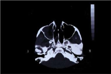
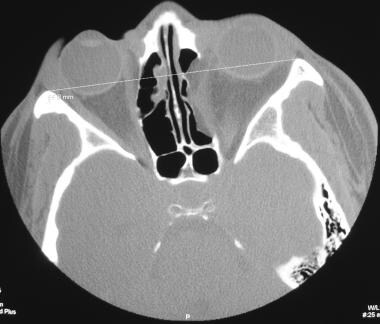
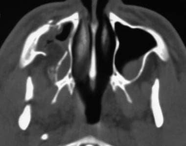 Axial computed tomography view shows a displaced bony fragment and herniation of orbital fat in the maxillary sinus.
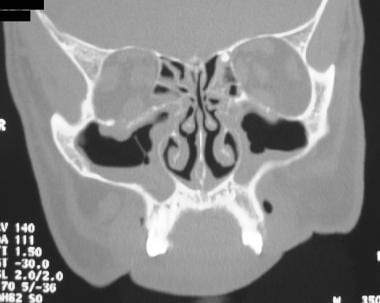
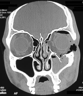 Computed tomography image depicting fractures of the left medial and inferior orbital wall associated with extensive orbital emphysema.
 Fractures of the medial and lateral orbital walls. This computed tomography image shows encroachment on lateral rectus muscle secondary to the lateral-wall fracture.
With blow-out fractures of the orbital floor, CT scanning can directly depict the degree of enophthalmos, if any. Direct visualization of extraocular muscles aids in determining whether the inferior rectus muscle is hooked or entrapped in an orbital floor fracture, if a similar injury to the medial rectus muscle against a medial wall fracture is present (uncommon), or if an injury has occurred to the superior rectus muscle with fracture of the orbital roof (rare). (See the following images.)
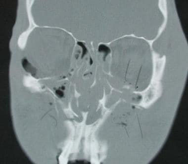
 Tripod fracture involving the fracture of the left orbital floor, which involves the infraorbital foramen. Note air (orbital emphysema) in the inferior orbit secondary to communication with the maxillary sinus.
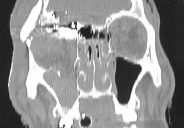
Computed tomography scan showing bilateral fractures of the orbital floor associated with a Le Fort II injury.
Tripod fracture involving the fracture of the left orbital floor, which involves the infraorbital foramen. Note air (orbital emphysema) in the inferior orbit secondary to communication with the maxillary sinus.
Computed tomography scan showing bilateral fractures of the orbital floor associated with a Le Fort II injury.
 Computed tomography scan demonstrating a fracture of the orbital floor involving both inferior and medial walls, resulting in a depressed fragment.
Fractures of the medial and lateral orbital walls. This computed tomography image shows encroachment on lateral rectus muscle secondary to the lateral-wall fracture.
Computed tomography scan demonstrating a fracture of the orbital floor involving both inferior and medial walls, resulting in a depressed fragment.
Fractures of the medial and lateral orbital walls. This computed tomography image shows encroachment on lateral rectus muscle secondary to the lateral-wall fracture.
 Computed tomography scan depicting fracture of the medial wall of the orbit, with deformity of the lamina papyracea. Note the medial herniation of orbital fat and muscle into the deformity. See also the next image.
 Coronal computed tomography view from a patient with a fracture of the medial wall of the orbit, with deformity of the lamina papyracea and medial herniation of orbital fat and muscle into the deformity.
CT scanning also permits the visualization of globe injuries, such as lens dislocation. [19] Retrobulbar hematoma and subperiosteal hematomas may be observed as well. With orbital roof fractures, coronal CT scans can display possible associated herniation of intraorbital contents into the frontal sinus or anterior cranial fossa. [20]
The development of multidetector-row/multisection (MDMS) spiral CT scanning has dramatically increased imaging speed and anatomic coverage. In addition, the development of true volumetric imaging has, in combination with technological progress in virtual reality, led to improved surgical simulation. [21] These advances have translated into better endovascular and surgical pretreatment planning.
Additionally, new generations of software have allowed soft tissues superficial to skeletal structures to be rendered or skin, muscle, and fat layers to be selectively removed to improve visualization of the targeted bones. Dimensional reconstruction of the facial structures has been especially useful in facial reconstruction planning. Contrast-enhanced MDCT angiography allows rapid vascular imaging to detect vascular compromise resulting from facial trauma.
A complete preoperative plan should be built on a comprehensive clinical examination of the periorbital soft-tissue and bony components, detailed ophthalmic examination, and high-resolution CT scans in the axial, coronal, and reformatted sagittal planes. On the basis of anatomic deformities, there are 2 major types of fracture that result in posttraumatic enophthalmos: orbital blow-out fractures and zygomatico-orbital fractures. [22, 23] Treatment modalities and methods of approach are adapted according to the severity of the orbital deformities. [24, 25, 26, 27, 28, 29, 30, 4]
Degree of confidence
CT scanning is the study of choice for orbital fractures, offering the highest degree of confidence. Thin-section coronal images provide an excellent depiction of all orbital walls, especially the floor and roof.
Axial imaging is good for evaluating fractures of the medial and lateral walls. The positioning is more comfortable for the patient, because this imaging is easily performed with the patient supine. However, axial imaging alone is not optimal for evaluating the orbital roof and floor; fractures along those structures and any displaced fragments are commonly in the same section plane and, therefore, are not ideally visualized.
False-positive fracture diagnosis can occur when suture lines and foramina are mistaken for fracture fissures. False-negative interpretation of images can result from unusual fracture lines directed in the same imaging plane, causing fracture nonvisualization.
Magnetic Resonance Imaging
MRI has a negligible role in the initial assessment of acute orbital injury because of its poor depiction of subtle bony detail and the overriding requirement that no metallic foreign bodies be present intraorbitally before exposing the patient to fluctuating magnetic fields. Such metallic foreign bodies can include bullet fragments or BB pellets left from an acute or previous penetrating trauma.
In an acute-trauma setting, the patient's history is often incomplete. In this case, bringing the patient into the magnetic resonance field is strictly contraindicated, because the individual may have been engaged in an occupation, such as sheet-metal work, that exposed him or her to flying metal debris. After the intraorbital presence of metal bodies has been excluded, preferably by means of CT scanning, MRI can be used for adjunct characterization of soft-tissue sequelae and complications of the above-described fractures.
As with CT scanning, MRI can demonstrate globe injuries, retrobulbar fluid collection (hematoma or other), subperiosteal hemorrhage, and hemorrhage along the optic nerve sheath, as well as the proximity of extraocular muscles to the fracture edges.
Because of its multiplanar capability, MRI is particularly useful in evaluating complications of orbital roof fractures, as these injuries can impact the undersurface of the frontal lobes, cause encephaloceles, or be associated with herniation of intraorbital contents into the anterior cranial fossa.
(Below are examples of CT images in which metallic foreign bodies are present, thus precluding MRI evaluation.)
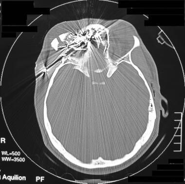 Computed tomography scan of a gross disruption of the right orbit secondary to a gunshot wound (GSW). Note the numerous metallic missile fragments retained. See also the next image.
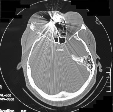
 Coronal computed tomography reconstruction demonstrates a gunshot wound (GSW) involving the superior orbital fracture. See also the next image.
 Computed tomography scan in a patient with a gunshot wound (GSW) involving the superior orbital fracture. This image shows metal fragments associated with a ruptured globe.
 Computed tomography scan showing a gunshot wound (GSW) to the left lateral orbit with associated bony fractures and metallic fragments in the lateral orbital compartment. See also the next image.
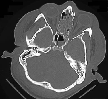
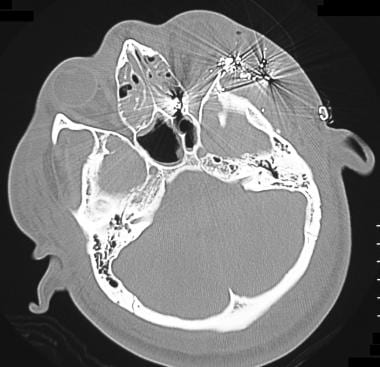
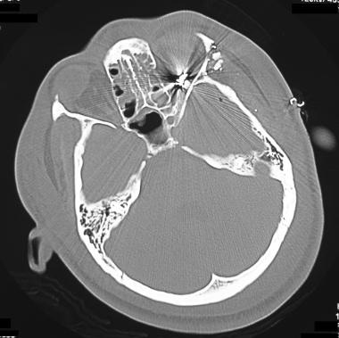 Computed tomography scan from a patient with a gunshot wound (GSW) to the left lateral orbit. This image shows metallic missile fragments in the orbital apex. See also the next image.
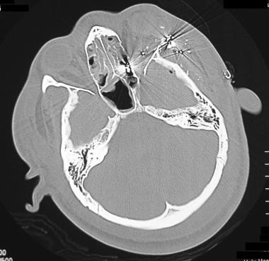 Computed tomography scan from a patient with a gunshot wound (GSW) to the left lateral orbit. This image shows intraconal emphysema and metallic fragments, including missile fragments in the posterior ethmoid.
Angiography
Selective catheterization of the external carotid arteries is necessary to identify vascular damage or a continued bleeding source caused by facial trauma. Thus, angiography can be pivotal when orbital trauma, whether internal or external, is related to facial bleeding. Traumatic changes to the facial artery or other branches of the external carotid artery can result in expanding hematomas or intense nasal cavity bleeding. Such injuries can be amenable to endovascular repair.
Head injuries in which the intracavernous carotid artery is torn can result in traumatic carotid-cavernous fistulas (CCFs). Such tears in the intracavernous carotid artery can cause redirected arterial flow into the ophthalmic veins, producing variable degrees of exophthalmos. Selective angiography of the internal carotid artery (ICA) can clearly display the presence or absence of a CCF.
(See the following angiograms from patients following trauma to head and/or face.)
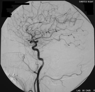
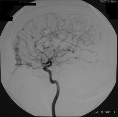
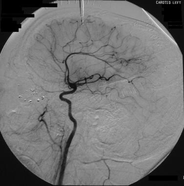 Left carotid angiogram from a patient with a gunshot wound (GSW) to the left lateral orbit. This image shows preservation of ophthalmic artery. See also the next image.
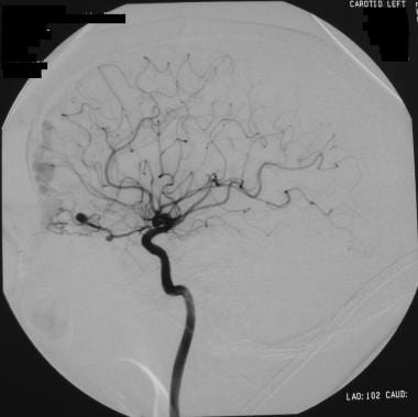
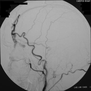
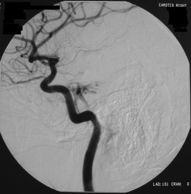 Selective right carotid angiogram from a patient with head trauma and an orbital bruit. This image shows a small carotid-cavernous fistula. See also the next image.
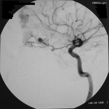
 One-month follow-up angiogram in a patient who had head trauma, an orbital bruit, and a small carotid-cavernous fistula. The carotid-cavernous fistula closed without intervention, as shown in this angiogram.
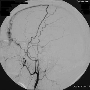
 Left internal carotid angiogram in a patient with a frontal dural fistula with repeated epistaxis. This image shows a feeder of the ophthalmic artery associated with 2 berry aneurysms. See also the next image.
 Angiogram in a patient with a frontal dural fistula with repeated epistaxis and a feeder vessel of the ophthalmic artery associated with 2 berry aneurysms. This image shows aneurysms. See also the next image.
 Selective left external carotid injection in a patient with a frontal dural fistula with repeated epistaxis and a feeder vessel of the ophthalmic artery associated with 2 berry aneurysms. This image shows a middle meningeal arterial feeder vessel. See also the next image.
 Selective right carotid angiogram in a patient with a frontal dural fistula with repeated epistaxis and a feeder vessel of the ophthalmic artery associated with 2 berry aneurysms. This image depicts the contribution of the right ophthalmic artery to the fistula. Venous aneurysm is present along the floor of the anterior cranial fossa. See also the next image.
 Selective right external carotid angiogram in a patient with a frontal dural fistula with repeated epistaxis and a feeder vessel of the ophthalmic artery associated with 2 berry aneurysms. This image shows a large feeder vessel of the right superficial temporal artery and extensive venous drainage.
-
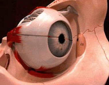
Eye and orbit.
-
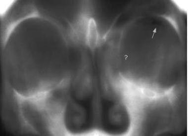
Conventional frontal tomograph of a blow-out fracture.
-
Coronal computed tomography scan shows a medial wall blow-out fracture of the right eye. Orbital fat is seen to herniate into the defect.
-
Tripod fracture involving the fracture of the left orbital floor, which involves the infraorbital foramen. Note air (orbital emphysema) in the inferior orbit secondary to communication with the maxillary sinus.
-
Axial computed tomography view shows a displaced bony fragment and herniation of orbital fat in the maxillary sinus.
-
Computed tomography image depicting fractures of the left medial and inferior orbital wall associated with extensive orbital emphysema.
-
Computed tomography scan showing bilateral fractures of the orbital floor associated with a Le Fort II injury.
-
Computed tomography scan demonstrating a fracture of the orbital floor involving both inferior and medial walls, resulting in a depressed fragment.
-
Fractures of the medial and lateral orbital walls. This computed tomography image shows encroachment on lateral rectus muscle secondary to the lateral-wall fracture.
-
Computed tomography scan depicting fracture of the medial wall of the orbit, with deformity of the lamina papyracea. Note the medial herniation of orbital fat and muscle into the deformity. See also the next image.
-
Coronal computed tomography view from a patient with a fracture of the medial wall of the orbit, with deformity of the lamina papyracea and medial herniation of orbital fat and muscle into the deformity.
-
Computed tomography scan of a gross disruption of the right orbit secondary to a gunshot wound (GSW). Note the numerous metallic missile fragments retained. See also the next image.
-
Coronal computed tomography reconstruction demonstrates a gunshot wound (GSW) involving the superior orbital fracture. See also the next image.
-
Computed tomography scan in a patient with a gunshot wound (GSW) involving the superior orbital fracture. This image shows metal fragments associated with a ruptured globe.
-
Computed tomography scan showing a gunshot wound (GSW) to the left lateral orbit with associated bony fractures and metallic fragments in the lateral orbital compartment. See also the next image.
-
Computed tomography scan from a patient with a gunshot wound (GSW) to the left lateral orbit. This image shows metallic missile fragments in the orbital apex. See also the next image.
-
Computed tomography scan from a patient with a gunshot wound (GSW) to the left lateral orbit. This image shows intraconal emphysema and metallic fragments, including missile fragments in the posterior ethmoid.
-
Left carotid angiogram from a patient with a gunshot wound (GSW) to the left lateral orbit. This image shows preservation of ophthalmic artery. See also the next image.
-
Selective right carotid angiogram from a patient with head trauma and an orbital bruit. This image shows a small carotid-cavernous fistula. See also the next image.
-
One-month follow-up angiogram in a patient who had head trauma, an orbital bruit, and a small carotid-cavernous fistula. The carotid-cavernous fistula closed without intervention, as shown in this angiogram.
-
Left internal carotid angiogram in a patient with a frontal dural fistula with repeated epistaxis. This image shows a feeder of the ophthalmic artery associated with 2 berry aneurysms. See also the next image.
-
Angiogram in a patient with a frontal dural fistula with repeated epistaxis and a feeder vessel of the ophthalmic artery associated with 2 berry aneurysms. This image shows aneurysms. See also the next image.
-
Selective left external carotid injection in a patient with a frontal dural fistula with repeated epistaxis and a feeder vessel of the ophthalmic artery associated with 2 berry aneurysms. This image shows a middle meningeal arterial feeder vessel. See also the next image.
-
Selective right carotid angiogram in a patient with a frontal dural fistula with repeated epistaxis and a feeder vessel of the ophthalmic artery associated with 2 berry aneurysms. This image depicts the contribution of the right ophthalmic artery to the fistula. Venous aneurysm is present along the floor of the anterior cranial fossa. See also the next image.
-
Selective right external carotid angiogram in a patient with a frontal dural fistula with repeated epistaxis and a feeder vessel of the ophthalmic artery associated with 2 berry aneurysms. This image shows a large feeder vessel of the right superficial temporal artery and extensive venous drainage.
-
The lateral wall of the orbit is formed by the frontal process of the zygomatic bone and the greater wing of the sphenoid bone.