Overview
Although EEG is designed to record cerebral activity, it also records electrical activities arising from sites other than the brain. The recorded activity that is not of cerebral origin is termed artifact and can be divided into physiologic and extraphysiologic artifacts. While physiologic artifacts are generated from the patient, they arise from sources other than the brain (ie, body). Extraphysiologic artifacts arise from outside the body (ie, equipment, environment). [1, 2, 3]
Physiologic Artifacts
Muscle (electromyogram) activity
Myogenic potentials are the most common artifacts (see images below). Frontalis and temporalis muscles (eg, clenching of jaw muscles) are common causes. Generally, the potentials generated in the muscles are of shorter duration than those generated in the brain and are identified easily on the basis of duration, morphology, and rate of firing (ie, frequency). Particular patterns of electromyogram (EMG) artifacts can occur in some movement disorders. Essential tremor and Parkinson disease can produce rhythmic 4- to 6-Hz sinusoidal artifacts that may mimic cerebral activity.
Another disorder that can produce repetitive muscle artifacts is hemifacial spasm. The photomyoclonic response is a special type of EMG artifact that occurs during intermittent photic stimulation. Some subjects contract the frontalis and orbicularis muscles. These contractions occur approximately 50-60 milliseconds after each flash, disappear after eye opening and use of paralyzers, are located mostly frontally, and have no concomitant EEG changes.
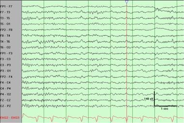
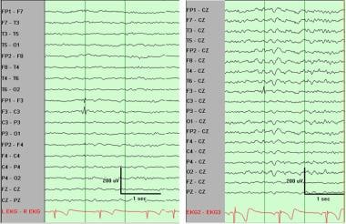
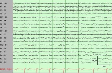 Electromyogram (muscle) artifact best observed in the left temporal region. ECG artifact also is present, best observed in the posterior region.
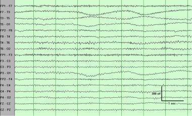
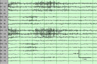 Electromyogram (muscle) artifact. These waveforms represent motor unit potentials as typically observed on needle electrode examination during electromyogram, with a frequency of 20-100 Hz. Distribution varies, and in this case it is more prominent on the left side. Such artifact can be diminished by the judicious use of the high-frequency filter. (This sample has the default setting of high-frequency filter 70 Hz.)
Glossokinetic artifact
In addition to muscle activity, the tongue (like the eyeball) functions as a dipole, with the tip negative with respect to the base. In this case, the tip of the tongue is the most important part because it is more mobile. The artifact produced by the tongue has a broad potential field that drops from frontal to occipital areas, although it is less steep than that produced by eye movement artifacts. The amplitude of the potentials is greater inferiorly than in parasagittal regions; the frequency is variable but usually in the delta range and occurs synchronously when the patient says "Lah-lah-lah-lah" or "Lilt-lilt-lilt-lilt," which can be verified by the technologist. Chewing and sucking can produce similar artifacts. These are commonly observed in young patients. However, they also can be observed in patients with dementia or those who are uncooperative.
Eye movements
Eye movements are observed on all EEGs and are useful in identifying sleep stages (see the Medscape Reference article Sleep Stage Scoring). The eyeball acts as a dipole with a positive pole oriented anteriorly (cornea) and a negative pole oriented posteriorly (retina). When the globe rotates about its axis, it generates a large-amplitude alternate current field, which is detectable by any electrodes near the eye. The other source of artifacts comes from EMG potentials from muscles in and around the orbit.
Vertical eye movements typically are observed with blinks (ie, Bell phenomenon). A blink causes the positive pole (ie, cornea) to move closer to frontopolar (Fp1-Fp2) electrodes, producing symmetric downward deflections. During downward eye movement the positive pole (ie, cornea) of the globe moves away from frontopolar electrodes, producing an upward deflection best recorded in channels 1 and 5 in the bipolar longitudinal montage.
Lateral eye movements most affect lateral frontal electrodes F7 and F8 (see images below). During a left lateral eye movement, the positive pole of the globe moves toward F7 and away from F8. Using a bipolar longitudinal montage, maximum positivity in electrode F7 and maximum negativity in electrode F8 is recorded, and artifacts do not occur in channels 9 and 13 or 10 and 14. A so-called rectus lateralis may be present in electrode F7; it is observed best in the vertex reference montage. With right lateral eye movement, the opposite occurs.
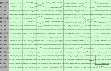 Eye movements such as these usually are observed in frontal electrodes and not further posteriorly than the midtemporal region. The phase reversals at lateral frontal electrodes F7 and F8 are of opposite polarity, indicating lateral eye movements. Because the cornea is charged positively and the retina negatively, the side of the positivity indicates the direction of eye movement. Thus, the first one here is to the right.
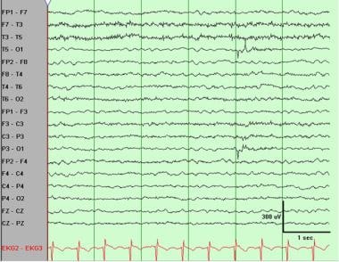
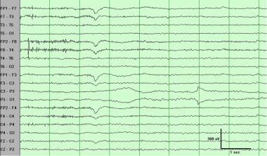
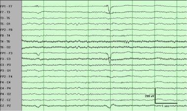 Left frontal artifact in the fourth second. This is not limited to a single electrode and has the morphology of an eye movement, but it is unilateral. This is an eye movement in a patient who has a glass right eye.
ECG artifact
Some individual variations in the amount and persistence of ECG artifact are related to the field of the heart potentials over the surface of the scalp. Generally, people with short and wide necks have the largest ECG artifacts on their EEGs. The voltage and apparent surface of the artifact vary from derivation to derivation and, consequently, from montage to montage. The artifact is observed best in referential montages using earlobe electrodes A1 and A2.
ECG artifact is recognized easily by its rhythmicity/regularity and coincidence with the ECG tracing (each "sharp wave" equals artifact that synchronizes with each QRS complex of the ECG channel; see image below). The situation becomes difficult when cerebral abnormal activity (eg, sharp waves) appears intermixed with EEG artifact, and the former may be overlooked. The EEG technologist should apply electrodes routinely to record the ECG.
 Regular (periodic) slow waves best observed at midtemporal and posterior temporal electrodes T4-T6 and T3-T5. These clearly are related to ECG. The duration and morphology are those of pulse artifact, but as demonstrated by the marker, no delay occurs between the ECG and the artifact. Thus, this is an ECG artifact with broad QRS complexes.
Pulse
Pulse artifact occurs when an EEG electrode is placed over a pulsating vessel. The pulsation can cause slow waves that may simulate EEG activity. A direct relationship exists between ECG and the pulse waves. The QRS complex (ie, electrical component of the heart contraction) happens slightly ahead of the pulse waves (200-300 millisecond delay after ECG equals QRS complex).
Respiration artifacts
Respiration can produce 2 kinds of artifacts. One type is in the form of slow and rhythmic activity, synchronous with the body movements of respiration and mechanically affecting the impedance of (usually) one electrode. The other type can be slow or sharp waves that occur synchronously with inhalation or exhalation and involve those electrodes on which the patient is lying. Several commercially available devices to monitor respiration can be coupled to the EEG machine. As with the ECG, one channel can be dedicated to respiratory movements. The simplest way to monitor respiration is by the EEG technician making notations with a pencil (ie, upward movement of the pencil for inhalations, downward return for exhalations).
Skin artifacts
Biological processes and/or defects may alter impedance and cause artifacts. Sweat is a common cause. Sodium chloride and lactic acid from sweating reacting with metals of the electrodes may produce huge slow baseline sways.
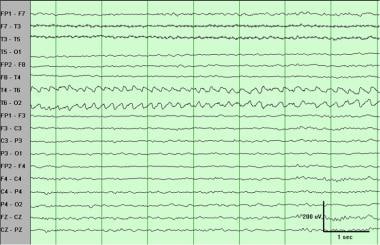
 Sweat artifact. This is characterized by very low-frequency (here, 0.25- to 0.5-Hz) oscillations. The distribution here (midtemporal electrode T3 and occipital electrode O1) suggests sweat on the left side. Note that morphology and frequency are also consistent with slow rolling eye movements, but distribution is not.
Significant asymmetry also can be observed when a collection (eg, subgaleal hematoma) is under or in the skin. In this last example, the amplitude of the background rhythm is reduced in derivations from electrodes overlying the hematoma.
Skull defects also can be the source of asymmetry. In this situation, amplitudes are greater in derivations from electrodes overlying or adjacent to skull defects.
Extraphysiologic Artifacts
Electrodes
The most common electrode artifact is the electrode popping. Morphologically this appears as single or multiple sharp waveforms due to abrupt impedance change. It is identified easily by its characteristic appearance (ie, abrupt vertical transient that does not modify the background activity) and its usual distribution, which is limited to a single electrode. In general, sharp transients that occur at a single electrode should be considered artifacts until proven otherwise.
Sweat artifact. This is characterized by very low-frequency (here, 0.25- to 0.5-Hz) oscillations. The distribution here (midtemporal electrode T3 and occipital electrode O1) suggests sweat on the left side. Note that morphology and frequency are also consistent with slow rolling eye movements, but distribution is not.
At other times, the impedance change is not so abrupt, and the artifact may mimic a low-voltage arrhythmic delta wave.
 Electrode artifact at frontal pole electrode Fp1. The duration is too short ("narrow") for any cerebral potential, and the distribution is limited to a single electrode (Fp1). In general, activity that affects a single electrode (ie, without the expected drop off and activity at neighboring electrodes or "plausible field") should be considered an artifact until proven otherwise.
 Electrode artifact at occipital electrode O1. The morphology is very unusual for any cerebral waveform, and the distribution is limited to a single electrode. In general, activity that affects a single electrode (ie, without the expected drop off and activity at neighboring electrodes or "plausible field") should be considered an artifact until proven otherwise.
 Electrode artifact at frontal electrode F3. This should not be misinterpreted as a spike. This sharply contoured transient clearly occurs at only one electrode, as confirmed on the referential montage.
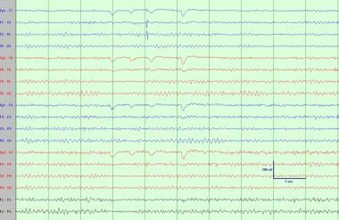
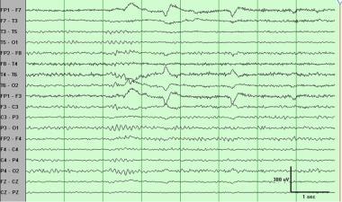
 Electrode (impedance) artifact at parietal electrode P3. Initially, a slow artifact is followed by a more abrupt one at the seventh second. This commonly is referred to as an electrode pop. Note again the unusual morphology of the sharp component and that it is at a single electrode. Also note an eye blink in the third second and slight electromyogram artifact in the frontal regions in the first 2 seconds.
 Just as electrode artifacts can simulate interictal spikes, they also can mimic an ictal pattern. This rhythmic artifact may be mistaken for an electrographic seizure or subclinical rhythmic epileptiform discharges of adults (SREDA). However, this is confined to a single electrode (posterior temporal electrode T6), as can be confirmed on a referential montage. This artifact often is confirmed by the presence of other definite electrode pops in the same electrode.
Alternating current (60-Hz) artifact
Adequate grounding on the patient has almost eliminated this type of artifact from power lines. The problem arises when the impedance of one of the active electrodes becomes significantly large between the electrodes and the ground of the amplifier. In this situation, the ground becomes an active electrode that, depending on its location, produces the 60-Hz artifact (see image below). The artifact presents at exact frequency (60 Hz, as its name indicates). A better identification can be made by increasing the paper speed (ie, sweep time) to 60 mm/s and counting it (1 cycle per millimeter).
 Ground recording artifact. This is a somewhat less common electrode artifact, also related to accidentally high impedance. The high impedance at posterior temporal electrode T6 results in this electrode recording from the ground on the forehead, thus picking up eye movements (which normally should not be observed at T6).
Movements in the environment
Movement of other persons around the patient can generate artifacts, usually of capacitive or electrostatic origin. Avoid this type of artifact as much as possible. If avoidance is not possible, as in the ICU and the operating room, place proper notation on the records.
Another artifact, probably due to electrostatic changes on the drops, can be introduced by a gravity-fed intravenous infusion. Morphologically this appears as spike transient potentials at fixed intervals that coincide with drops of the infusion.
With the increasing use of automatic electric infusion pumps, a new type of artifact, infusion motor artifact (IMA), has arisen. Morphologically, IMA appears as very brief spiky transients, sometimes followed by a slow component of the same polarity. Its frequency does not relate directly to drop rate. Lininger et al have suggested that this artifact arises from electromagnetic sources. [4]
The artifact produced by respirators varies widely in morphology and frequency. Monitoring the ventilator rate in a separate channel helps to identify this type of artifact.
Interference from high-frequency radiation from radio, television, hospital paging systems, and other electronic devices can overload EEG amplifiers. The pens may deflect upward or downward to full excursion, and no EEG can be recorded. The cutting and/or coagulating electrode used in the operating room also generates high-voltage high-frequency signals that interfere with the recording system. The best thing to do is turn off the EEG machine while using this instrument.
Patient Education
For patient education resources, see the Procedures Center, as well as Electroencephalography (EEG).
Questions & Answers
Overview
What are EMG artifacts on EEG?
What are Glossokinetic artifacts on EEG?
How do eye movement appear on EEG?
What are ECG artifacts on EEG?
When does a pulse artifact occur on EEG?
What are respiration artifacts on EEG?
What are skin artifacts on EEG?
What are electrode artifacts on EEG?
What are alternating current (60-Hz) artifacts on EEG?
Which artifacts on EEG are caused by electrostatic changes?
What are infusion motor artifacts (IMA) on EEG?
Which artifacts on EEG are caused by respirators?
Which artifacts on EEG are caused by high-frequency radiation?
-
Electromyogram (muscle) artifact best observed in the left temporal region. ECG artifact also is present, best observed in the posterior region.
-
Electromyogram (muscle) artifact. These waveforms represent motor unit potentials as typically observed on needle electrode examination during electromyogram, with a frequency of 20-100 Hz. Distribution varies, and in this case it is more prominent on the left side. Such artifact can be diminished by the judicious use of the high-frequency filter. (This sample has the default setting of high-frequency filter 70 Hz.)
-
Eye movements such as these usually are observed in frontal electrodes and not further posteriorly than the midtemporal region. The phase reversals at lateral frontal electrodes F7 and F8 are of opposite polarity, indicating lateral eye movements. Because the cornea is charged positively and the retina negatively, the side of the positivity indicates the direction of eye movement. Thus, the first one here is to the right.
-
Left frontal artifact in the fourth second. This is not limited to a single electrode and has the morphology of an eye movement, but it is unilateral. This is an eye movement in a patient who has a glass right eye.
-
Regular (periodic) slow waves best observed at midtemporal and posterior temporal electrodes T4-T6 and T3-T5. These clearly are related to ECG. The duration and morphology are those of pulse artifact, but as demonstrated by the marker, no delay occurs between the ECG and the artifact. Thus, this is an ECG artifact with broad QRS complexes.
-
Sweat artifact. This is characterized by very low-frequency (here, 0.25- to 0.5-Hz) oscillations. The distribution here (midtemporal electrode T3 and occipital electrode O1) suggests sweat on the left side. Note that morphology and frequency are also consistent with slow rolling eye movements, but distribution is not.
-
Electrode artifact at frontal pole electrode Fp1. The duration is too short ("narrow") for any cerebral potential, and the distribution is limited to a single electrode (Fp1). In general, activity that affects a single electrode (ie, without the expected drop off and activity at neighboring electrodes or "plausible field") should be considered an artifact until proven otherwise.
-
Electrode artifact at occipital electrode O1. The morphology is very unusual for any cerebral waveform, and the distribution is limited to a single electrode. In general, activity that affects a single electrode (ie, without the expected drop off and activity at neighboring electrodes or "plausible field") should be considered an artifact until proven otherwise.
-
Electrode artifact at frontal electrode F3. This should not be misinterpreted as a spike. This sharply contoured transient clearly occurs at only one electrode, as confirmed on the referential montage.
-
Electrode (impedance) artifact at parietal electrode P3. Initially, a slow artifact is followed by a more abrupt one at the seventh second. This commonly is referred to as an electrode pop. Note again the unusual morphology of the sharp component and that it is at a single electrode. Also note an eye blink in the third second and slight electromyogram artifact in the frontal regions in the first 2 seconds.
-
Just as electrode artifacts can simulate interictal spikes, they also can mimic an ictal pattern. This rhythmic artifact may be mistaken for an electrographic seizure or subclinical rhythmic epileptiform discharges of adults (SREDA). However, this is confined to a single electrode (posterior temporal electrode T6), as can be confirmed on a referential montage. This artifact often is confirmed by the presence of other definite electrode pops in the same electrode.
-
Ground recording artifact. This is a somewhat less common electrode artifact, also related to accidentally high impedance. The high impedance at posterior temporal electrode T6 results in this electrode recording from the ground on the forehead, thus picking up eye movements (which normally should not be observed at T6).