Overview
Evoked potentials are the electrical signals generated by the nervous system in response to sensory stimuli. Auditory, visual, and somatosensory stimuli are used commonly for clinical evoked potential studies. Somatosensory evoked potentials (SEPs) consist of a series of waves that reflect sequential activation of neural structures along the somatosensory pathways. While SEPs can be elicited by mechanical stimulation, clinical studies use electrical stimulation of peripheral nerves, which gives larger and more robust responses.
The stimulation sites typically used for clinical diagnostic SEP studies are the median nerve at the wrist, the common peroneal nerve at the knee, and the posterior tibial nerve at the ankle. SEPs can also be recorded following stimulation of branches of the trigeminal nerve, but this is technically challenging because of the proximity of the stimulating and recording electrodes and the short latencies of the responses; the electrical stimulus artifact often overlaps with, and obscures, the trigeminal nerve SEPs. Recordings of SEPs to stimulation of the ulnar nerves at the wrists are useful for intraoperative monitoring when the mid-cervical spinal cord or parts of the brachial plexus are at risk. Recording electrodes are placed on the scalp, over the spine, and over peripheral nerves proximal to the stimulation site.
SEPs are used for clinical diagnosis in patients with neurologic diseases, to evaluate patients with sensory sympotoms that might be psychogenic, for prognostication in comatose patients, and for intraoperative monitoring during surgeries that place parts of the somatosensory pathways at risk. Abnormal SEPs can result from dysfunction at the level of the peripheral nerve, plexus, spinal root, spinal cord, brain stem, thalamocortical projections, or primary somatosensory cortex. Since individuals have multiple parallel afferent somatosensory pathways (e.g., the anterior spinothalamic tract and the dorsal column tracts within the spinal cord), SEPs can be normal in patients with significant sensory deficits. However, an abnormal SEP result demonstrates that there is dysfunction within the somatosensory pathways; subjects cannot volitionally make their SEPs abnormal.
The SEP components generated in the brainstem and in the cerebral cortex are mediated entirely by the dorsal columns (posterior columns) of the spinal cord, the fasciculus cuneatus for upper limb SEPs and the fasciculus gracilis for lower limb SEPs. Lesioning of the dorsal columns of the spinal cord rostral to the root levels where the afferent somatosensory activity enters the spinal cord abolishes the SEPs generated in the brain. SEPs can persist following lesions of the anterolateral spinal cord, however. SEPs are abnormal in diseases of the dorsal columns in which joint position sense and proprioception are impaired.
The development of, and easy access to, sophisticated neuroradiologic imaging has had a great impact on the usage of SEPs in clinical settings; fewer diagnostic SEP studies are being performed now than in the pre-MRI era. Nevertheless, SEPs are valuable as a diagnostic test in several clinical situations, and as a prognostic tool in patients who are comatose as a result of anoxic brain injury. Their role in the operating room has expanded, and interest remains high in SEPs as research tools for unraveling of fundamental aspects of sensory physiology.
An overview of the general principles of recording and interpretation of SEPs is presented in this article.
Electrical Stimulation Parameters
Stimulus location
For recording median nerve SEPs, the nerve is stimulated at the wrist. The anode is placed just proximal to the palmar crease, and the cathode is placed between the tendons of the palmaris longus muscle, 3 cm proximal to the anode.
Ulnar nerve SEPs are preferred to median nerve SEPs for assessing the lower cervical spinal cord, especially during intraoperative monitoring when this part of the spinal cord is at risk, because the ulnar nerve originates from spinal roots C8-T1, whereas the median nerve originates from C6-T1. Ulnar nerve SEPs will detect dorsal column damage at the C7-C8 level, but the median nerve SEPs may persist, mediated by sensory fibers that enter the spinal cord at the C6 level.
For recording posterior tibial nerve SEPs, the nerve is stimulated at the ankle, with the cathode midway between the Achilles tendon and the medial malleolus and the anode 3 cm distal to the cathode.
For recording peroneal nerve SEPs, the common peroneal nerve is stimulated at the knee, with the cathode inferior to the leg crease just medial to the tendon of the biceps femoris muscle and the anode 3 cm distal to the cathode.
In the lower limb, posterior tibial SEPs are generally preferred because of the following:
-
In clinical diagnostic use, they are larger and display less intrasubject variability.
-
In intraoperative settings, they produce less patient movement.
-
In intraoperative settings, electrodes at the ankle are more accessible, and thus more easily replaced should they malfunction, than those at the knee.
-
The peripheral nerve compound action potential (CAP) can be recorded at the popliteal fossa and can be used to determine whether the nerve is being adequately stimulated. This is crucial when the rostral SEPs deteriorate during intraoperative monitoring, to indicate whether the SEP changes are caused by spinal cord compromise or by technical problems with nerve stimulation.
However, peroneal nerve stimulation may be better in some cases because of the following:
-
Duing clinical diagnostic testing, some patients can tolerate peroneal nerve stimulation but find posterior tibial nerve stimulation too uncomfortable.
-
The posterior tibial nerve may be difficult or impossible to stimulate adequately in some patients, because of adiposity at the ankle, casting, amputation, etc.
-
In some patients with peripheral neuropathy (which may tends to affect longer nerves more severely), peroneal nerve SEPs may be present whereas no posterior tibial nerve SEPs are identifiable.
Stimulus duration and intensity
The selected nerves are stimulated with monophasic square pulses, 100-300 microseconds in duration. Stimuli are delivered by using either a constant voltage or a constant current stimulator.
The contact impedances of the stimulating electrodes should be kept low for the following reasons:
-
To minimize patient discomfort
-
For more effective nerve stimulation, if a constant voltage stimulator is used
-
To minimize the electrical stimulus artifacts in the recorded data
In the clinical setting, the stimulus intensity is set high enough to produce a consistent muscle twitch, which usually is tolerable to the patient. Because the patient is anesthetized during intraoperative SEP monitoring, higher stimulus intensities can be used and are advisable to provide a safety margin in case the efficacy of nerve stimulation decreases during surgery. Factors that can decrease the efficacy of nerve stimulation include edema of the limb, partial short-circuiting of the stimulating current by fluids, and ischemia of the peripheral nerve. [1]
Stimulus rate
Rapid stimulus delivery rates should be avoided, as they degrade the SEP waveforms. In clinical settings, a rate of 3-6 stimuli per second is usually used. Rates that are exact subharmonics of the line frequency (eg, 5.0 Hz) should be avoided, since their use would lead to contamination of the averaged SEPs by large artifacts of the line frequency (50 or 60 Hz). Signal averaging reduces noise that is random with respect to stimulus delivery while retaining signals that are time-locked to stimulus delivery. If the stimulus rate is an exact subharmonic of the line frequency, the inevitable line-frequency noise will be at the same phase in each data epoch, and will be preserved rather than eliminated during the averaging process.
Recording Parameters
Extraoperative SEPs typically are recorded by using standard EEG electrodes affixed with tape or collodion; electrode caps containing multiple recording electrodes also can be used. Scalp needle electrodes are not used routinely for diagnostic SEP studies but are often used for intraoperative monitoring when the patient is anesthetized.
Recording electrode impedances should be kept below 5,000 ohms and should be as uniform as possible across the electrodes to maximize common-mode rejection and minimize noise pickup. Also, placing the ground electrodes on the stimulated limb, proximal to the stimulation site, helps to reduce the electrical stimulant artifact.
Typical recording amplifier filter settings for SEPs are 5-30 Hz (low-cut or high-pass filter) to 3,000 Hz (high-cut or low pass filter). Diagnostic SEP studies should be performed using the same filter settings that were used to record the normative data.
SEPs are composed of both low and high frequencies, and filtering can be problematic. A bandpass that is too wide results in noisy SEPs, but a bandpass that is too restrictive attenuates either high- or low-frequency components, depending on the settings chosen, and distorts the SEP waveform. For example, reducing the low-frequency filter setting (low-cut, high-pass) from 30 to 5 Hz may produce a larger and clearer cortical SEP component but also may allow more low-frequency noise into the SEP waveforms.
A typical analysis time is 40 milliseconds for an upper limb SEP and 60-80 milliseconds for a lower limb SEP. During intraoperative monitoring, longer analysis times (e.g., 50 and 100 milliseconds, respectively) may be useful, as component latencies may be prolonged by hypothermia, anesthesia, and pathology. [2]
SEPs are typically not visible in the raw data recorded from surface electrodes, and signal averaging is used to extract the SEPs from the other electrical signals picked up by the recording electrodes. Online artifact rejection is used to prevent epochs with unusually high noise levels from contaminating the averages. Sedation also may be used to reduce artifacts due to muscle and patient movement. Sleep causes minor changes in the SEP waveforms.
A negativity at input 1 with respect to input 2 is usually displayed as an upward deflection in the SEP waveform, but this polarity convention is not uniform across all laboratories performing SEP recordings.
Measurement of Somatosensory Evoked Potentials
Several characteristics of SEPs can be measured, including peak latencies, component amplitudes, and waveform morphology. Peak latencies are consistent across subjects, whereas amplitudes show large intersubject variability. Therefore, interpretation of extraoperative diagnostic SEP studies is predominantly based on peak latencies and measures derived from them, such as interpeak intervals and right-left differences. Component amplitudes are more consistent during repeated SEP recordings in the same subject and may change sooner than latencies change, or in the absence of any latency changes, if the somatosensory pathways are damaged during surgery. Therefore, both peak latencies and component amplitudes should be measured and followed during intraoperative monitoring. [3]
Absolute SEP latencies vary with limb length. Interpeak intervals are useful because they separate out effects of limb length and of peripheral nerve disease, which may prolong absolute SEP latencies in the absence of central nervous system pathology. Aging is associated with some prolongation of SEP latencies. Latencies are considered abnormal when they are more than either 2.5 or 3 standard deviations above the mean of the normative data (depending on the laboratory's conventions).
Recording electrodes sites
Recording electrode sites are identified by anatomical landmarks. Those on the head are defined using the international 10-20 system, or its extension, the 10-10 system. Electrode CP3 is midway between C3 and P3, and electrode CP4 is midway between C4 and P4. CPi denotes either CP3 or CP4, whichever is ipsilateral to the stimulated limb; CPc is the contralateral centroparietal scalp electrode. CPz is midway between Cz and Pz.
Recording electrodes over the spine are placed in the midline and can be labeled with the name of the vertebral body they are placed over followed by the letter S, for example, C5S or T10S.
Recording montages for cortical SEP components are either cephalic bipolar, in which both electrodes are placed over the head, or referential, in which a reference electrode is placed at a noncephalic site. Cephalic bipolar montages yield signals with less noise contamination and are preferred for routine clinical use.
For upper limb SEP studies, electrodes are placed over Erbs point (ie, the angle between the clavicular head of the sternocleidomastoid muscle and the clavicle), both ipsilateral and contralateral to the stimulus (labeled EPi and EPc, respectively). For lower limb SEP studies, IC denotes an electrode placed over an iliac crest.
Montages for the upper limb SEPs
The minimal montage recommended by the American EEG Society (AEEGS, currently the American Clinical Neurophysiology Society) for recording of upper limb SEPs is as follows:
-
Channel 4 - CPc-Cpi
-
Channel 3 - CPi-EPc
-
Channel 2 - C5S-EPc
-
Channel 1 - EPi-EPc
An example of a median nerve SEP recorded with this montage is shown in the image below.
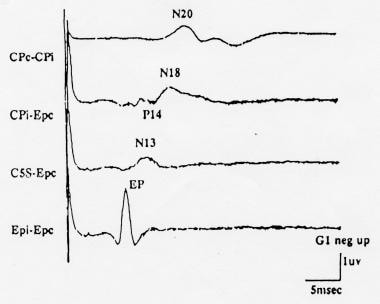 Normal median nerve somatosensory evoked potentials (SEPs) recorded using the minimal (4-channel) recording montage recommended by the American EEG Society (AEEGS) guidelines. Negativity at input 1 is shown as an upward deflection. Courtesy of American Electroencephalographic Society, 1994.
Montages for lower limb SEPs
The minimal montage recommended by the AEEGS for recording of lower limb SEPs is as follows:
-
Channel 4 - CPi-Fpz
-
Channel 3 - CPz-Fpz
-
Channel 2 - Fpz-C5S
-
Channel 1 - T12S-IC
An example of a posterior tibial nerve SEP recorded with this montage is shown in the image below.
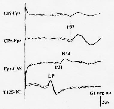 Normal posterior tibial nerve somatosensory evoked potentials (SEPs) recorded using the minimal (4-channel) recording montage recommended by the American EEG Society (AAEGS) guidelines. Note that the second channel from the bottom is specified as Fpz-C5S, so that the far-field potentials appear as a P31 followed by an N34. Negativity at input 1 is shown as an upward deflection. Courtesy of American Electroencephalographic Society, 1994.
This montage does not include a channel for recording the peripheral nerve CAPs at the popliteal fossa. Thus, optimal recording of lower limb SEPs requires more than 4 channels; a signal average with at least 8 input channels offers the advantage that all channels can be recorded simultaneously.
Spinal SEP
Spinal SEPs are recorded by electrodes placed on the skin surface over the spine as described above. They are considerably smaller in amplitude than SEPs recorded over the scalp. However, the difference in latency between the scalp and the cervical or limb SEPs is a measure of central sensory conduction, assessment of which remains the chief clinical goal of recording SEPs. Thoracolumbar spinal SEPs are even smaller than cervical spinal SEPs and can be difficult to record, especially in obese subjects.
Components of Somatosensory Evoked Potentials
Nomenclature of Evoked-Potential Components
SEP components typically are named by their polarity and typical peak latency in the normal population. For example, N20 is a negativity that typically peaks at 20 milliseconds after the stimulus. The normal latency value for a component in a particular individual may be different from that implied by the component's name, because the lengths of the peripheral nerve and spinal conduction pathways, which vary with the patient's stature, influence the latencies of the SEP components. [4]
The nomenclature of an evoked-potential component is inconsistent in the literature because the recording montage is not specified with the peak latency and polarity. For example, a CPi-EPc linkage following median nerve stimulation records a P14, while an EPc-CPi linkage records an N14. Also, the primary cortical SEP to median nerve stimulation, most often called N20, is sometimes referred to as N19 because of its mean latency in the author's control population.
Upper Limb Somatosensory Evoked Potentials
Peripheral nerve compound action potential
During clinical diagnostic studies of the upper limb SEP, a surface electrode at Erbs point is used to record the peripheral nerve CAP as it traverses the brachial plexus. N9, the initial negative peak (labeled EP in the image below), reflects the CAP within the most rapidly conducting subset of the afferent fibers. Multiple negative peaks, reflecting peripheral nerve fiber populations with different conduction velocities, may be recorded in some subjects, most often in children. When this occurs, the earliest negative peak should be interpreted as the N9 peak. A smaller P9 far-field peak, which most likely also arises within the brachial plexus, may be seen in scalp-to-noncephalic recordings; it has a slightly shorter latency than N9.
Normal median nerve somatosensory evoked potentials (SEPs) recorded using the minimal (4-channel) recording montage recommended by the American EEG Society (AEEGS) guidelines. Negativity at input 1 is shown as an upward deflection. Courtesy of American Electroencephalographic Society, 1994.
Erbs point-recording electrodes have several disadvantages during intraoperative monitoring, such as their proximity to the sterile field, ease of dislodgment, and pickup of ECG artifact. A useful alternative recording site is over the peripheral nerve in the antecubital fossa (see image below).
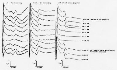 Somatosensory evoked potentials (SEPs) recorded during resection of a posterior fossa tumor (intradural extension of a clear-cell tumor of the right middle ear) in a 46-year-old woman. The peripheral nerve compound action potentials (CAPs) to left median nerve stimulation, recorded at the elbow, and the simultaneously recorded cortical SEPs both displayed marked amplitude attenuation. The stimulating electrodes at the left wrist were replaced; the peripheral nerve and cortical SEPs both returned to their baseline values and remained there through the end of the operation. Courtesy of Legatt, 1995.
Cervical components
An SEP component that most likely arises in the first-order afferent neuron at or near the dorsal root entry zone (ie, in the dorsal root and/or the dorsal column) can be recorded as a far-field P11 peak in scalp-to-noncephalic reference recordings and as a near-field N11 peak in surface recordings over the lower cervical spine. This component is small, and it is not identifiable in all healthy subjects. [5]
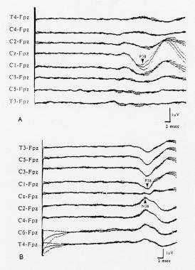
A larger and more consistent component recorded over the lower cervical spine (eg, at SC5 or SC7) is N13. N13 has a horizontally oriented voltage field, negative dorsally and positive ventrally (see image below), and is generated by postsynaptic activity of neurons in the gray matter of the lower cervical spinal cord. It sometimes is called the stationary cervical potential, because its latency is not affected by changes in the cervical recording electrode location. [6]
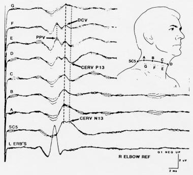 Somatosensory evoked potentials (SEPs) to stimulation of the left median nerve, recorded from a ring of electrodes placed around the neck at the level of SC5 posteriorly and the superior border of the thyroid cartilage anteriorly. Courtesy of Emerson et al, 1984.
Far-field components
The stationary cervical potential overlaps in time with a far-field SEP component, P14. The dipole orientation of P14 is such that it appears as a positive peak in recordings between the dorsal scalp (input 1) and a noncephalic electrode (input 2) (see image below). While the origin of P14 has been the subject of some controversy, it most likely reflects activity in the dorsal column nuclei and/or the caudal medial lemniscus within the lower medulla. When a forehead (ie, Fpz) reference is used, this far-field cervicomedullary component becomes a negativity (N14) at the C5S recording location and summates with the near-field N13 negativity picked up by that dorsal neck electrode. [7]
Normal median nerve somatosensory evoked potentials (SEPs) recorded using the minimal (4-channel) recording montage recommended by the American EEG Society (AEEGS) guidelines. Negativity at input 1 is shown as an upward deflection. Courtesy of American Electroencephalographic Society, 1994.
The presence of overlapping negative peaks in the C5S-Fpz recording channel (a channel that was recommended in older SEP guidelines), may make attenuation of one of them difficult or impossible to recognize. Thus, as mentioned above, this recording channel has been replaced by separate C5S-Epc and Cpi-Epc recording channels in the minimal montage recommended in the most recent set of AEEGS guidelines.
For intraoperative monitoring, the cervicomedullary far-field potential may be recorded between the forehead (Fpz) and the inion, mastoid, or earlobe; this montage prevents contamination by, and confusion with, the N13 component. Depending on which electrode is designated as input 1, the cervicomedullary SEP component may be recorded as either an N14 or a P14. This component can be monitored to determine whether activity in afferent somatosensory pathways reaches the level of the cervicomedullary junction (see image below).
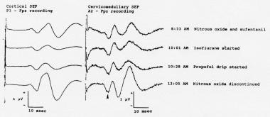 Cortical (left) and cervicomedullary N14 (right) somatosensory evoked potentials (SEPs) to stimulation of the right median nerve, recorded during the initial phases of surgery for resection of a right vestibular schwannoma. The cortical SEPs show prominent anesthetic-related changes. While the waveforms recorded in the A2-Fpz channel contain some volume-conducted cortical SEPs, the N14 far-field component (arrowhead) is unaffected by the changes in the anesthetic regimen. Courtesy of Legatt, 1995.
Anesthesia affects the cortical SEP (N20) more than it does the N14 component, because at least 2 more synapses (in thalamus and cortex) intervene. Therefore, monitoring of the cervicomedullary SEP may permit SEP monitoring of the cervical spinal cord when cortical SEPs are of poor quality because of high anesthetic levels and/or preexisting neuronal damage.
If the region of the nervous system in jeopardy is rostral to the medulla, the cervicomedullary SEP component can be monitored to determine whether changes in the cortical SEPs are due to rostral nervous system dysfunction versus peripheral nerve or technical problems. This is similar to the intraoperative use of the peripheral nerve SEP component described above. Optimally, both components should be monitored for 2 reasons: (1) the cervicomedullary SEP provides an alternative way of differentiating the possible causes of a cortical SEP change if peripheral nerve SEP recordings are suboptimal, and (2) if peripheral nerve CAPs are interpretable and remain unchanged while cortical SEPs deteriorate, examination of the cervicomedullary recordings can localize further the neural dysfunction responsible for the cortical SEP changes above or below the foramen magnum.
Another far-field component, N18, overlaps in time with the primary cortical SEP and may account for multiple negative peaks in the cortical recordings in some subjects (see image below). N18 has a wide bilateral distribution over the scalp. It is best seen in recordings with a noncephalic reference, though it also may be demonstrated with a frontal reference. While N18 has been attributed to a thalamic generator, several cases have been reported in which N18 was still present despite the presence of thalamic lesions that eradicated the primary cortical SEP. N18 most likely reflects activity in multiple subcortical structures that are activated by the somatosensory stimulus, including brainstem structures. Thus, examination of N18 cannot be used to localize the cause for cortical SEP changes (as being rostral versus caudal to the thalamus).
Normal median nerve somatosensory evoked potentials (SEPs) recorded using the minimal (4-channel) recording montage recommended by the American EEG Society (AEEGS) guidelines. Negativity at input 1 is shown as an upward deflection. Courtesy of American Electroencephalographic Society, 1994.
Cortical components
The primary cortical SEP component following median nerve stimulation, N20 (see image above), is recorded as a near-field potential over the parietal area contralateral to the stimulated median nerve. Since an electrode also is within the scalp distribution of the far-field N18 component, a recording with a noncephalic reference contains an admixture of N18 and N20. The recommended montage places the reference over the mirror-image position ipsilateral to the stimulus (ie, a CPc-CPi recording linkage), which tends to cancel the bilaterally distributed N18. An Fz reference also has been used to record N20 but may yield a composite waveform consisting of N20 and the inversion of the frontally generated P22 component. A CPc-Fz or CPc-Fpz linkage may be useful for intraoperative monitoring because it yields a cortical SEP waveform that is larger in amplitude than the CPc-CPi linkage used for diagnostic recordings.
While a thalamic or subcortical origin for N20 has been suggested, most authors believe that N20 predominantly reflects activity of neurons in the hand area of the primary somatosensory cortex; multiple generators with overlapping voltage topographies may contribute to this component. N20 predominantly originates in primary somatosensory cortex in the posterior bank of the central sulcus (see first image below) and thus displays a polarity inversion across the central sulcus in epidural cortical surface recordings (see second image below) and some scalp recordings. This polarity inversion may be used to identify the central sulcus during surgery.
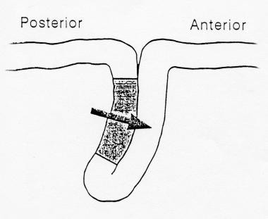 Diagram showing generation of the N20 component of the median nerve somatosensory evoked potentials (SEP) in the primary somatosensory cortex located in the posterior bank of the central sulcus producing a horizontal dipole with a postcentral N20 and precentral P20.
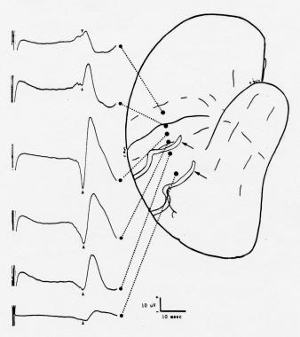 Somatosensory evoked potentials (SEPs) to median nerve stimulation recorded from cortical surface electrodes prior to resection of a right parietal arteriovenous malformation (AVM) in a 35-year-old man. Note the inversion of the N20/P20 component (arrowheads) across the central sulcus; the amplitude is largest over the postcentral gyrus, where the component is negative in polarity. The longer latency surface-positive component has a different distribution. The arrows indicate 2 large veins draining the AVM. Courtesy of Legatt, 1991.
An accumulation of air within the subarachnoid space can block the volume conduction of the cortically generated SEP components to the overlying recording electrodes; this is most likely when the patient is in the sitting position and cerebrospinal fluid (CSF) has been drained. The peripheral nerve and far-field cervicomedullary SEPs are generally not affected. Therefore, the SEP changes produced by pneumocephalus can mimic those caused by intraoperative compromise of the somatosensory pathways rostral to the cervicomedullary junction.
Lower Limb Somatosensory Evoked Potentials
Peripheral nerve compound action potential
A surface electrode placed in the popliteal fossa in the midline can be used to record the peripheral nerve CAP following posterior tibial nerve stimulation at the ankle. To minimize both electrical stimulus artifact and ECG pickup, a reference electrode on the same leg is used. Possible linkages include a midline electrode 2 cm above the popliteal crease referred to a midline electrode 5 cm above the popliteal crease and a midline popliteal fossa electrode referred to an electrode placed at the lateral aspect of the same knee.
In patients in whom a clear foot twitch is not obtained, the presence of a clear peripheral nerve CAP at the popliteal fossa demonstrates that the posterior tibial nerve has been stimulated adequately. In this case, the absence of more rostrally generated SEP components is evidence of abnormality within the neural somatosensory pathways. Without the peripheral nerve recording channel, the absence of rostral SEPs also could have been due to technical factors that prevented adequate nerve stimulation. Similarly, during intraoperative monitoring, examination of the peripheral nerve recording channel permits a rapid classification of the causes of changes in the more rostrally generated SEP components.
Lumbar components
An electrode placed over the lower thoracic or upper lumbar spine records a combination of the CAP in the primary afferent neuron, propagating within the cauda equina and fasciculus gracilis, and a stationary lumbar potential (SLP) that is derived from postsynaptic neurons in the gray matter of the spinal cord. Recordings with a distant reference, such as the iliac crest, emphasize the SLP, which is analogous to the stationary cervical potential (N13) recorded over the lower cervical spine following median nerve stimulation.
Bipolar recordings between a pair of rostrocaudally separated electrodes over the lower spine record the propagating CAP. However, they also contain a component derived from the SLP, representing the difference in the amplitude of the SLP between the 2 recording electrodes. The relative magnitudes of the CAP and SLP contributions vary across subjects; therefore, referential recordings show less intersubject latency variability and should be used for clinical diagnostic SEP testing.
The normal amplitude maximum of the SLP is at the T10-T12 vertebral level but may be fairly restricted (see image below).
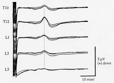 Somatosensory evoked potentials (SEPs) recorded simultaneously over multiple vertebral levels to posterior tibial nerve stimulation, with an iliac crest reference. The amplitude of the stationary lumbar potential (SLP) is maximal at the T12 level. Negativity at input 1 is shown as an upward deflection. Courtesy of Legatt et al, 1986.
Thus, referential recordings from multiple electrodes over the lumbar and lower thoracic spine may be useful in demonstrating the SLP. The following channels are included in an extended montage suggested in the AEEGS guidelines:
-
T10-IC
-
T12-IC
-
L2-IC
In patients with tethered spinal cords, recordings from such an array of electrodes often demonstrate caudal displacement of the maximal amplitude of the SLP, reflecting the anatomical displacement of the lower spinal cord, or may show no identifiable SLP. The lumbar SEP components are sometimes not identifiable in unsedated healthy subjects, especially if they are obese.
Far-field components
When referred to a frontal scalp reference (eg, Fpz), electrodes over the cervical spine record a biphasic waveform that was labeled originally as a cervical potential but is believed now to reflect predominantly far-field potentials generated in subcortical elements of the lemniscal somatosensory pathways. If the inputs are connected so that the cervical lead is input 1 (ie, C5S-Fpz), the waveform consists of a negativity followed by a positivity. [7]
The montage given in the AEEGS guidelines specifies this channel as an Fpz-C5S recording, with Fpz as input 1. Such a recording contains a positivity followed by a negativity, which are designated P31 and N34, respectively, following posterior tibial nerve stimulation (see image below); the peak latencies are approximately 10 milliseconds shorter, following peroneal nerve stimulation. P31 is analogous to the P14 component of the median nerve SEP and, like it, most likely is generated in the dorsal column nuclei and/or the caudal medial lemniscus within the lower medulla. The negativity that follows is most likely analogous to the N18 component of the median nerve SEP and thus is generated by activity in multiple brainstem and/or thalamic structures that are activated by the somatosensory stimulus.
Normal posterior tibial nerve somatosensory evoked potentials (SEPs) recorded using the minimal (4-channel) recording montage recommended by the American EEG Society (AAEGS) guidelines. Note that the second channel from the bottom is specified as Fpz-C5S, so that the far-field potentials appear as a P31 followed by an N34. Negativity at input 1 is shown as an upward deflection. Courtesy of American Electroencephalographic Society, 1994.
A near-field origin within the cervical spinal cord had been proposed for some smaller and earlier peaks that can be picked up by the recording electrodes placed on the posterior part of the neck. Like the lumbar SEP components, the far-field SEP components elicited by lower limb nerve stimulation may be difficult to identify in recordings from unsedated subjects because of noise, particularly electromyogram (EMG) artifact from paraspinal musculature. Under surgical anesthesia, and especially with the use of neuromuscular blocking agents, these SEP components are usually clearly identifiable and reproducible.
The cortically generated SEPs elicited by stimulation of lower limb nerves are far more sensitive to the effects of anesthesia than the far-field components (see image below). During operations in which the cortically generated SEPs are markedly attenuated or completely suppressed by anesthesia or in which they show a degree of anesthetic-related variability such that changes related to surgical manipulations might not be recognized, the far-field SEPs may be used to monitor the dorsal column pathways of the spinal cord.
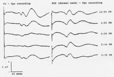 Serial somatosensory evoked potentials (SEPs) recorded during spinal instrumentation and fusion surgery in a 13-year-old girl with scoliosis. Note the attenuation of the cortical SEPs resulting from administration of an intravenous bolus dose of 50 mg of fentanyl given at 1:53 pm. The far-field SEPs were relatively unaffected. In addition to the far-field components, the C2S-Fpz waveforms (labeled "SC2-Fpz") contain a volume-conducted contribution from the cortical SEPs; the contribution also was attenuated by the fentanyl. Nitrous oxide (60%) and isoflurane (0.6-0.8%) were being administered throughout these recordings. Positivity at input 1 is shown as an upward deflection in this picture.
Cortical components
The primary cortical SEPs following lower limb stimulation are recorded as near-field positivities: P37 following posterior tibial nerve stimulation and P27 following peroneal nerve stimulation. In contrast to the N20 cortical component of the median nerve SEP, which is maximal over the lateral parietal area, the cortical SEPs to lower limb nerve stimulation often are maximal near the midline, reflecting the more medial location of the foot and leg areas of the somatosensory homunculus. However, the topography of these components varies across subjects, reflecting individual differences in the location and orientation of somatosensory cortex (see image below) and may differ between the 2 sides in the same subject.
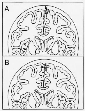 Diagram showing 2 possible locations for the foot area of the somatosensory homunculus (shaded area of cerebral cortex), which generates the P37 cortical component of the posterior tibial somatosensory evoked potential (SEP). The arrows represent the equivalent dipoles of the cortical SEP generators; the arrowhead marks the positive side of the dipole field. A: The maximum P37 amplitude is in the midline. B: The maximum P37 amplitude is over the hemisphere ipsilateral to the stimulus, and the negativity can be recorded over the contralateral hemisphere.
When the equivalent dipole of the cortical generator is oriented vertically, the maximum positivity is in the midline (see A in the image above; also see the image below). When the cortical generator is located in the mesial wall of the hemisphere, the dipole assumes a more horizontal orientation, producing a paradoxical maximum positive cortical SEP over the hemisphere ipsilateral to the stimulus (see B in the image above; also see B in the image below).
 Cortical somatosensory evoked potentials (SEPs) to stimulation of the left posterior tibial nerve in 2 different healthy subjects, showing the variability of scalp topography. The SEPs were recorded from the coronal chain of electrodes; negativity at the active electrode as compared to the Fpz reference is shown as an upward deflection. A: The cortical positivity (labeled "P38") is maximal in the midline at the vertex. B: The cortical positivity is maximal over the hemisphere ipsilateral to the stimulus and is inverted to a negativity over the contralateral hemisphere. Courtesy of Emerson, 1988.
In the latter situation, a negative cortical SEP may be recorded over the contralateral hemisphere, and a midline electrode may pick up a much smaller and less well-defined cortical SEP. Rarely, the activated cortex is on the dorsolateral convexity, producing a scalp positivity maximum over the hemisphere contralateral to the stimulated leg. To cover all of these possibilities, the extended recording montage suggested in the AEEGS guidelines includes the following cortical recording channels:
-
CPc-Fpz
-
CPz-Fpz
-
Cpi-Fpz
When the dipole is oriented horizontally, producing an ipsilateral positivity and a contralateral negativity, a CPi-CPc recording channel may yield a larger cortical SEP than any of the recordings referred to Fpz. Thus, some laboratories incorporate a Cpi-CPc derivation in their recording montage. However, the latencies of the ipsilateral positivity and the contralateral negativity may not be identical, and the Cpi-CPc SEP may be a composite potential reflecting multiple cortical sources. Thus, a Cpi-CPc SEP should be compared only to normative data recorded with the same derivation.
Since the largest cortical SEP is located at CPz in some patients, while in others with a more horizontal dipole a small cortical SEP is recordable at this electrode but a substantial SEP can be recorded over the ipsilateral hemisphere, the optimal cortical SEP recording electrode sites may differ from patient to patient. If the monitoring equipment does not permit simultaneous recording from multiple channels (eg, CPz-FPz and CPi-FPz), the electrode derivations used for intraoperative monitoring should be customized on the basis of the results of the patient's preoperative SEP studies. However, CPz-Fpz and CPz-CPc are the most recommended cortical channels. [8] Therefore these preoperative studies must include recordings of the cortical SEPs from both midline and lateral electrodes.
With both peroneal nerve and posterior tibial nerve stimulation, longer latency cortical SEP components follow the primary cortical P27 or P37 components. The second cortical positivity, which typically has a latency of 50-60 milliseconds after posterior tibial nerve stimulation, may be substantially larger than the primary cortical SEP (see image below). In noisy recordings with a limited montage, a low-amplitude P37 component may not be recognized, and the secondary cortical positivity may be identified erroneously as a markedly delayed cortical SEP (see Pz-Fpz waveforms in the image below). Thus, cortical SEPs to lower limb nerve stimulation should be interpreted with caution when their peak latencies appear to be delayed abnormally to this latency range.
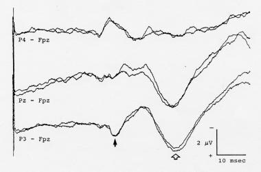 Cortical somatosensory evoked potentials (SEPs) to left posterior tibial nerve stimulation, showing a secondary cortical positivity (open arrow) that is much larger than the P37 primary cortical SEP component (solid arrow). If only a single Pz-Fpz channel were used to record the cortical SEP, the secondary component might be identified erroneously as a markedly delayed cortical SEP. Negativity at input 1 is shown as an upward deflection.
Near-field Spinal Somatosensory Evoked Potentials
In some patients who are undergoing surgery for lesions that have already caused spinal cord dysfunction, both cortical and far-field SEPs may be absent in surface recordings because of a combination of anesthetic effects and temporal dispersion of the afferent volley. Electrodes positioned close to the spinal cord may pick up reproducible near-field SEPs, permitting intraoperative monitoring. Because the spinal cord volley in these patients is desynchronized and/or because the near-field electrode picks up activity in several different fiber populations, the SEPs picked up by electrodes on the dorsal surface of the spinal cord often are complex and polyphasic. This may preclude simple latency and amplitude measurements, but SEP changes caused by manipulation of the spinal cord or irrigation with cold fluids still can be recognized (see image below).
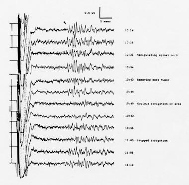 Desynchronized, polyphasic somatosensory evoked potentials (SEPs) to posterior tibial nerve stimulation, recorded from the spinal cord during removal of an intradural extramedullary neuroma that was compressing the spinal cord in a 44-year-old woman. Cervical SEPs were highly inconsistent and not suitable for monitoring; cortical SEPs were absent. The bipolar recording electrodes were placed on the dorsal surface of the spinal cord rostral to the lesion. Note the reversible changes with manipulation of the spinal cord and with irrigation of the cord with cold fluids. Courtesy of Legatt, 1991.
Interpretation of Somatosensory Evoked Potentials
Spinal cord pathways mediating the somatosensory evoked potentials
The large-fiber, rapidly conducting afferent somatosensory pathways that sustain the primary cortical SEPs to stimulation of mixed sensorimotor limb nerves travel predominantly in the dorsal columns (fasciculus gracilis and fasciculus cuneatus) within the spinal cord.
In experimental animals, transection of the dorsal column pathways almost completely obliterates the earliest cortical SEPs to stimulation of nerves whose axons enter the spinal cord caudal to the transection, while ventrolateral funiculus lesions usually have only minor effects on these SEPs. Thus, significant damage to descending motor systems can occur without causing changes in the SEPs used for intraoperative monitoring. Such false-negative cases are fortunately rare, but they have occurred. In contrast to the cortical SEPs, near-field SEPs recorded over the spinal cord (see image below) may contain components reflecting large-fiber afferent activity in both the dorsal columns and the spinocerebellar tracts.
Desynchronized, polyphasic somatosensory evoked potentials (SEPs) to posterior tibial nerve stimulation, recorded from the spinal cord during removal of an intradural extramedullary neuroma that was compressing the spinal cord in a 44-year-old woman. Cervical SEPs were highly inconsistent and not suitable for monitoring; cortical SEPs were absent. The bipolar recording electrodes were placed on the dorsal surface of the spinal cord rostral to the lesion. Note the reversible changes with manipulation of the spinal cord and with irrigation of the cord with cold fluids. Courtesy of Legatt, 1991.
Clinical diagnostic studies
SEP amplitudes may vary considerably across subjects, and the interpretation of clinical diagnostic SEP studies is based primarily on component latencies. For upper limb SEPs, the AEEGS guidelines include identification of the obligate components N9, N13, P14, N18, and N20. Measurement of the N9-N20, N9-P14, and P14-N20 interpeak intervals is specified; interpeak intervals involving the N13 component are listed as options. The N9-P14 interpeak interval measures neural conduction from the brachial plexus to the lower medulla, P14-N20 from the lower medulla to primary somatosensory cortex, and N9-N20 from the brachial plexus to primary somatosensory cortex. The N13 component reflects activity within the lower cervical spinal cord. Absolute component latencies are less useful than interpeak intervals because of the effect of arm length on the latencies of N9 and subsequent components.
For posterior tibial nerve SEPs, the AEEGS guidelines mandate at minimum the identification of the SLP and the primary cortical SEP component (P37), measurement of their peak latencies, and calculation of the SLP-P37 interpeak interval. The latter approximates the conduction time between the lumbar spinal cord and primary somatosensory cortex. Some laboratories also measure the latency of the initial far-field component (P31) and calculate SLP-P31 and P31-P37 interpeak latencies, corresponding to lumbar spinal cord-to-medulla and medulla-to-primary somatosensory cortex conduction times, respectively.
For lower limb SEPs, conduction distances along both the peripheral nerve and the spinal cord portions of the afferent pathway vary considerably among subjects as a function of height. Some laboratories use height-adjusted norms for the analysis of lumbar SEP components; others measure the conduction distances and calculate conduction velocities. When no height corrections are used, interpeak latencies should be interpreted with caution in patients whose heights are at the extremes of the range of heights for which the normative data were collected.
The major criteria for abnormality are absence of obligate components and abnormal prolongation of interpeak intervals. As with any evoked-potential test involving unilateral stimulation, excessive symmetries between the measurements following left-sided stimulation and those following right-sided stimulation also may reveal abnormalities. The stationary cervical/stationary lumbar and cervicomedullary far-field components may be difficult to identify in some healthy subjects who are not sedated. In the presence of normal cortical SEPs, the inability to identify some of the more caudally generated SEP components may not be significant.
SEPs in comatose patients
In adults who are comatose following a cerebral anoxic insult (eg, due to a cardiopulmonary arrest), absence of the N20 (cortical) component of the median nerve SEP following stimulation of either median nerve predicts a bad outcome (death or persistent vegetative state) with virtually 100% specificity. [9] Preservation of the SEPs does not, however, ensure a good outcome, as patients may have extensive brain injury despite preservation of the afferent somatosensory pathways and primary somatosensory cortex, or they may die from other disease processes (eg, cardiac disease that caused the arrest). [10] On the other hand, presence of the N20 is a light predictor for good outcome. [11] In patients treated with targeted temperature management (TTM), absence of the SEPs may not predict poor outcome. [12, 13]
Bilateral absence of the N20 is also associated with poor outcomes in adult patients with coma due to traumatic brain injury, although some of these patients may recover consciousness if the absence of SEPs was due to a focal lesion that interrupted the pathway between the peripheral nerve and somatosensory cortex. Patients comatose from other causes such as infection and metabolic derangements may also have better outcomes despite bilateral absence of N20 on initial examination.
Intraoperative monitoring
A comprehensive discussion of the interpretation of intraoperative evoked potential data is beyond the scope of this presentation and the reader is referred to other sources. When surgical maneuvers compromise neural tissue, SEP components may show significant amplitude attenuation before their latencies become prolonged. Thus, both amplitudes and latencies should be evaluated during intraoperative monitoring. No universally accepted standard exists for what constitutes a significant change, but a 50% decrease in the amplitude of an SEP component or a 10% increase in its latency often are used as alarm threshold criteria. The differences in the percentages reflects the fact that SEP amplitudes generally show more run-to-run variability than do SEP latencies.
Whenever the SEPs change, the interpreter must distinguish between the many possible causes of such a change, which include anesthetic effects and technical factors as well as true neuronal damage or dysfunction. As discussed above, recordings of peripheral nerve CAPs and cervicomedullary far-field potentials can help elucidate the causes and significance of changes in cortical SEPs during intraoperative SEP monitoring for both upper limb and lower limb SEPs.
Anesthetic agents are probably the most common cause of intraoperative SEP changes. In general, the longer the latency of an SEP component and the more synapses between the stimulation site and the component's neural generator, the greater is the degree to which that component will be affected by anesthetic agents. Thus, anesthetic effects may alter the cortical SEPs while sparing the far-field SEPs (see images below), mimicking surgery-related dysfunction of the cerebral cortex or of the pathways from the brain stem to the cerebral cortex. Personnel performing intraoperative monitoring must pay careful attention to the anesthetic regimen and should record it periodically on their data logs.
Cortical (left) and cervicomedullary N14 (right) somatosensory evoked potentials (SEPs) to stimulation of the right median nerve, recorded during the initial phases of surgery for resection of a right vestibular schwannoma. The cortical SEPs show prominent anesthetic-related changes. While the waveforms recorded in the A2-Fpz channel contain some volume-conducted cortical SEPs, the N14 far-field component (arrowhead) is unaffected by the changes in the anesthetic regimen. Courtesy of Legatt, 1995.
Serial somatosensory evoked potentials (SEPs) recorded during spinal instrumentation and fusion surgery in a 13-year-old girl with scoliosis. Note the attenuation of the cortical SEPs resulting from administration of an intravenous bolus dose of 50 mg of fentanyl given at 1:53 pm. The far-field SEPs were relatively unaffected. In addition to the far-field components, the C2S-Fpz waveforms (labeled "SC2-Fpz") contain a volume-conducted contribution from the cortical SEPs; the contribution also was attenuated by the fentanyl. Nitrous oxide (60%) and isoflurane (0.6-0.8%) were being administered throughout these recordings. Positivity at input 1 is shown as an upward deflection in this picture.
Personnel performing intraoperative monitoring also should periodically note and log the temperature and blood pressure of the patient, which also can affect the electrophysiologic signals. Anesthetic-induced changes typically are bilateral; this can help distinguish anesthetic-related from surgery-related SEP changes when the latter are expected to be unilateral (eg, during carotid endarterectomy) but not when surgical manipulations can damage afferent sensory pathways bilaterally (eg, bilateral spinal cord damage during surgery for scoliosis). Peripheral and rostral or contralateral cortical SEPs should help to exclude non-iatrogenic etiology. [14] Area under the curve (AUC) of the SEPs may help to promtly detect intra-operative spinal cord damage. [15]
SEPs in children
The cortical SEP to posterior tibial nerve stimulation may be absent in healthy infants as old as 3 months. The cortical SEP to median nerve stimulation also may be absent at birth but most likely is present consistently in healthy infants at an earlier age than the corresponding component of the lower limb SEP. SEP component latencies are, in general, shorter in infants and children than in adults and change progressively with growth and maturation. The latency changes predominantly reflect linear growth with elongation of the peripheral nerves and central somatosensory pathways. These effects are counterbalanced partially by myelination and increase in the fiber diameters, which produce faster conduction velocities, and partially by maturation of synaptic transmission. The latter effects operate until age 6-8 years, at which time central conduction times have reached adult levels and further latency changes are due to changes in stature. [16, 17]
During spinal surgery in children in whom cortical SEPs are absent or easily attenuated by anesthesia, the far-field SEP components may be used to monitor the dorsal column pathway of the spinal cord. However, many patients with lumbar meningomyeloceles have conduction abnormalities (eg, conduction blocks, temporal dispersion) at the level of the neural plaque so that both far-field and cortical SEPs are absent; this precludes intraoperative assessment of the dorsal column pathways in these patients.
Questions & Answers
Overview
What are somatosensory evoked potentials (SEPs)?
How are median nerve somatosensory evoked potentials (SEPs) recorded?
How are ulnar nerve somatosensory evoked potentials (SEPs) recorded?
How are posterior tibial nerve somatosensory evoked potentials (SEPs) recorded?
How are peroneal nerve somatosensory evoked potentials (SEPs) recorded?
Why are posterior tibial nerve somatosensory evoked potentials (SEPs) preferred in the lower limb?
What are the duration and intensity of somatosensory evoked potentials (SEPs)?
What is the stimulus rate of electrical stimulation of somatosensory evoked potentials (SEPs)?
What are the recording parameters of somatosensory evoked potentials (SEPs)?
What characteristics of somatosensory evoked potentials (SEPs) are measured?
How are electrodes placed for somatosensory evoked potentials (SEPs)?
How are spinal somatosensory evoked potentials (SEPs) recorded?
What is the nomenclature of somatosensory evoked potentials (SEPs) components?
What are the cervical components of upper limb somatosensory evoked potentials (SEPs)?
What are the far-field components of upper limb somatosensory evoked potentials (SEPs)?
What are the cortical components of upper limb somatosensory evoked potentials (SEPs)?
What are the lumbar components of lower limb somatosensory evoked potentials (SEPs)?
What are the far-field components of lower limb somatosensory evoked potentials (SEPs)?
What are the cortical components of lower limb somatosensory evoked potentials (SEPs)?
What is near-field somatosensory evoked potentials (SEPs)?
What are the spinal cord pathways mediating the somatosensory evoked potentials (SEPs)?
How are diagnostic somatosensory evoked potentials (SEPs) interpreted?
How are somatosensory evoked potentials (SEPs) interpreted in comatose patients?
What is the role of somatosensory evoked potentials (SEPs) in intraoperative monitoring?
How do somatosensory evoked potentials (SEPs) findings in children differ from adults?
-
Normal median nerve somatosensory evoked potentials (SEPs) recorded using the minimal (4-channel) recording montage recommended by the American EEG Society (AEEGS) guidelines. Negativity at input 1 is shown as an upward deflection. Courtesy of American Electroencephalographic Society, 1994.
-
Normal posterior tibial nerve somatosensory evoked potentials (SEPs) recorded using the minimal (4-channel) recording montage recommended by the American EEG Society (AAEGS) guidelines. Note that the second channel from the bottom is specified as Fpz-C5S, so that the far-field potentials appear as a P31 followed by an N34. Negativity at input 1 is shown as an upward deflection. Courtesy of American Electroencephalographic Society, 1994.
-
Somatosensory evoked potentials (SEPs) recorded during resection of a posterior fossa tumor (intradural extension of a clear-cell tumor of the right middle ear) in a 46-year-old woman. The peripheral nerve compound action potentials (CAPs) to left median nerve stimulation, recorded at the elbow, and the simultaneously recorded cortical SEPs both displayed marked amplitude attenuation. The stimulating electrodes at the left wrist were replaced; the peripheral nerve and cortical SEPs both returned to their baseline values and remained there through the end of the operation. Courtesy of Legatt, 1995.
-
Somatosensory evoked potentials (SEPs) to stimulation of the left median nerve, recorded from a ring of electrodes placed around the neck at the level of SC5 posteriorly and the superior border of the thyroid cartilage anteriorly. Courtesy of Emerson et al, 1984.
-
Cortical (left) and cervicomedullary N14 (right) somatosensory evoked potentials (SEPs) to stimulation of the right median nerve, recorded during the initial phases of surgery for resection of a right vestibular schwannoma. The cortical SEPs show prominent anesthetic-related changes. While the waveforms recorded in the A2-Fpz channel contain some volume-conducted cortical SEPs, the N14 far-field component (arrowhead) is unaffected by the changes in the anesthetic regimen. Courtesy of Legatt, 1995.
-
Diagram showing generation of the N20 component of the median nerve somatosensory evoked potentials (SEP) in the primary somatosensory cortex located in the posterior bank of the central sulcus producing a horizontal dipole with a postcentral N20 and precentral P20.
-
Somatosensory evoked potentials (SEPs) to median nerve stimulation recorded from cortical surface electrodes prior to resection of a right parietal arteriovenous malformation (AVM) in a 35-year-old man. Note the inversion of the N20/P20 component (arrowheads) across the central sulcus; the amplitude is largest over the postcentral gyrus, where the component is negative in polarity. The longer latency surface-positive component has a different distribution. The arrows indicate 2 large veins draining the AVM. Courtesy of Legatt, 1991.
-
Somatosensory evoked potentials (SEPs) recorded simultaneously over multiple vertebral levels to posterior tibial nerve stimulation, with an iliac crest reference. The amplitude of the stationary lumbar potential (SLP) is maximal at the T12 level. Negativity at input 1 is shown as an upward deflection. Courtesy of Legatt et al, 1986.
-
Serial somatosensory evoked potentials (SEPs) recorded during spinal instrumentation and fusion surgery in a 13-year-old girl with scoliosis. Note the attenuation of the cortical SEPs resulting from administration of an intravenous bolus dose of 50 mg of fentanyl given at 1:53 pm. The far-field SEPs were relatively unaffected. In addition to the far-field components, the C2S-Fpz waveforms (labeled "SC2-Fpz") contain a volume-conducted contribution from the cortical SEPs; the contribution also was attenuated by the fentanyl. Nitrous oxide (60%) and isoflurane (0.6-0.8%) were being administered throughout these recordings. Positivity at input 1 is shown as an upward deflection in this picture.
-
Diagram showing 2 possible locations for the foot area of the somatosensory homunculus (shaded area of cerebral cortex), which generates the P37 cortical component of the posterior tibial somatosensory evoked potential (SEP). The arrows represent the equivalent dipoles of the cortical SEP generators; the arrowhead marks the positive side of the dipole field. A: The maximum P37 amplitude is in the midline. B: The maximum P37 amplitude is over the hemisphere ipsilateral to the stimulus, and the negativity can be recorded over the contralateral hemisphere.
-
Cortical somatosensory evoked potentials (SEPs) to stimulation of the left posterior tibial nerve in 2 different healthy subjects, showing the variability of scalp topography. The SEPs were recorded from the coronal chain of electrodes; negativity at the active electrode as compared to the Fpz reference is shown as an upward deflection. A: The cortical positivity (labeled "P38") is maximal in the midline at the vertex. B: The cortical positivity is maximal over the hemisphere ipsilateral to the stimulus and is inverted to a negativity over the contralateral hemisphere. Courtesy of Emerson, 1988.
-
Cortical somatosensory evoked potentials (SEPs) to left posterior tibial nerve stimulation, showing a secondary cortical positivity (open arrow) that is much larger than the P37 primary cortical SEP component (solid arrow). If only a single Pz-Fpz channel were used to record the cortical SEP, the secondary component might be identified erroneously as a markedly delayed cortical SEP. Negativity at input 1 is shown as an upward deflection.
-
Desynchronized, polyphasic somatosensory evoked potentials (SEPs) to posterior tibial nerve stimulation, recorded from the spinal cord during removal of an intradural extramedullary neuroma that was compressing the spinal cord in a 44-year-old woman. Cervical SEPs were highly inconsistent and not suitable for monitoring; cortical SEPs were absent. The bipolar recording electrodes were placed on the dorsal surface of the spinal cord rostral to the lesion. Note the reversible changes with manipulation of the spinal cord and with irrigation of the cord with cold fluids. Courtesy of Legatt, 1991.
Tables

What would you like to print?
- Overview
- Electrical Stimulation Parameters
- Recording Parameters
- Measurement of Somatosensory Evoked Potentials
- Components of Somatosensory Evoked Potentials
- Near-field Spinal Somatosensory Evoked Potentials
- Interpretation of Somatosensory Evoked Potentials
- Questions & Answers
- Show All
- Media Gallery
- References